 Sign-up for free online course on ANSYS simulations!
| Include Page | ||||
|---|---|---|---|---|
|
| Include Page | ||||
|---|---|---|---|---|
|
Mesh
Create Mesh
| HTML |
|---|
<iframe width="560" height="315" src="https://www.youtube.com/embed/g-cHqbx9uRk" frameborder="0" allow="accelerometer; autoplay; encrypted-media; gyroscope; picture-in-picture" allowfullscreen></iframe> |
Increase Near-Wall Resolution
| HTML |
|---|
<iframe width="560" height="315" src="https://www.youtube.com/embed/oSP6Mh3A-Gs" frameborder="0" allow="accelerometer; autoplay; encrypted-media; gyroscope; picture-in-picture" allowfullscreen></iframe> |
Label Boundaries
| HTML |
|---|
<iframe width="560" height="315" src="https://www.youtube.com/embed/zvDWmwrPIMU" frameborder="0" allow="accelerometer; autoplay; encrypted-media; gyroscope; picture-in-picture" allowfullscreen></iframe> |
Go to all FLUENT Learning Modules
| Panel |
|---|
Problem Specification |
Step 3: Mesh
| Note | ||
|---|---|---|
| ||
We are working on updating this part of the tutorial. Please come back soon. |
...
In ANSYS Mesher, make sure that the unit we are working on is meter Metric unit. On the top menu, click on Units and make sure that Metric (m, kg, N, s, V, A) is selected.
...
Meshing Method
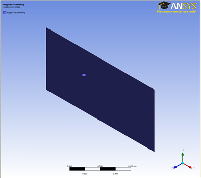
We would also like to create a structured mesh where the opposite edges correspond with each other. Let's insert a Mapped Face mesh. Under Outline, right click on Mesh, move cursor to Insert, and select Mapped Face Meshing. Alternatively, you can click on Mesh Control on the third menu and select Mapped Face Meshing. Finally select the flat plate surface body in the Graphics window and click Apply next to Geometry.
This is what you should end up with;
Edge Sizing
...
Now continue with the sizing in the axial direction.
...
We have specified all the meshing conditions. Click Update on the third menu to see the mesh.
Click on Mesh and look under Details of "Mesh", next to Statistics, you should see that we have 6120 Elements for our mesh.
Create Named Selection
Next, we will name the edges accordingly so that we can specify the appropriate boundary conditions in the later step. We know the bottom edges of the geometry are the centerline of the pipe, the left edge is the inlet of the pipe, the right edge is the outlet of the pipe, top side edges are wall and the top middle edge is the heated wall section. Let's name the edges according to the diagram below. Remember to click on the Edge tabon the Fluid flow Fluent - Mesh window and then press Ctrl + mouse click to multiple select the 3 line sections that make up the center line before naming it.
Select the left edge and right click and select Create Named Selection. Enter Inlet and click OK. Under Outline, you will see the name Inlet under Named Selections.
Finish naming rest of the edges. Finally, click Update .
Go to Step 4: Setup (Physics)