 Sign-up for free online course on ANSYS simulations!
| Include Page | ||||
|---|---|---|---|---|
|
| Include Page | ||||
|---|---|---|---|---|
|
Geometry
Launch ANSYS and Save
| HTML |
|---|
<iframe width="560" height="315" src="https://www.youtube.com/embed/XPm9FWMy0Rk" frameborder="0" allow="accelerometer; autoplay; encrypted-media; gyroscope; picture-in-picture" allowfullscreen></iframe> |
The link below takes you to the Cornell IT web page which explains how to link your google drive account while using Apps on Demand.
Link: https://it.cornell.edu/appsondemand/set-google-drive-file-stream-apps-demand
| Info |
|---|
MAE 3240 Spring 2020: At this point if you prefer, you can skip the geometry (step 2) and mesh (step 3) videos by downloading the file below and continuing to Model Setup (step 4) also linked below.
Completed Geometry and Mesh File: Flat_Plate_Mesh.wbpz
Model Setup Link: https://confluence.cornell.edu/x/ak0UBw |
Create Domain
| HTML |
|---|
<iframe width="560" height="315" src="https://www.youtube.com/embed/EGcooy3KCz4" frameborder="0" allow="accelerometer; autoplay; encrypted-media; gyroscope; picture-in-picture" allowfullscreen></iframe> |
Go to all FLUENT Learning Modules
| Panel |
|---|
Problem Specification |
Step 2: Geometry
Since our problem involves fluid flow, we will select the FLUENT component on the left panel.
Left click (and hold) on Fluid Flow (FLUENT), and drag the icon to the empty space in the Project Schematic. Here's what you get:
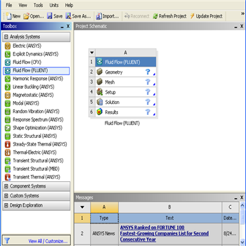
Since we selected Fluid Flow (FLUENT), each cell of the system corresponds to a step in the process of performing CFD analysis using FLUENT. Rename the project to Flat Plate Boundary Layer.
We will work through each step from top down to get to obtain the solution to our problem.
...
...
At this point, a new window, ANSYS Design Modeler will be opened. You will be asked to select desired length unit. Use the default meter unit and click OK.
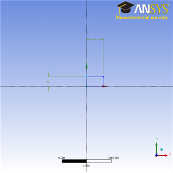
Creating a Sketch
...
In the Sketching toolboxes, select Rectangle. In the Graphicswindow, create a rough Rectangle from starting from the origin in the positive XY direction (Make sure that you see a letter P at the origin before you start dragging the rectangle. The letter P at the origin means the geometry is constrained at the origin.)
You should have something like this:
...
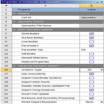
Dimensions
Now we will specify the appropriate dimensions and constraints. Below is the summary of geometry of the pipe:
Length: 1 m
Height: 0.5m
Under Sketching Toolboxes, select Dimensions tab, use the default dimensioning tools. Then click on the lines and drag upwards or sideways as the case may be to place the dimensions
Go to Step 3: Mesh