 Sign-up for free online course on ANSYS simulations!
| Wiki Markuppanel |
|---|
|
geometry
{color:#ff0000}{*} geometry Specify boundary conditions{*}{color}conditions |
Step
...
6:
...
Specify
...
boundary
...
conditions
...
Recall
...
that
...
the
...
BCs
...
for
...
face
...
1
...
are:
...
u=0
...
at
...
node
...
A
...
(keypoint
...
1)
...
v=0
...
at
...
all
...
face
...
1
...
nodes
...
w=0
...
along
...
AB
...
(line
...
L7)
...
These
...
BCs
...
are
...
in
...
the
...
cylindrical
...
coordinate
...
system.
...
Switch
...
to
...
this
...
coordinate
...
system:
...
Utility
...
Menu
...
>
...
WorkPlane
...
>
...
Change
...
Active
...
CS
...
to
...
>
...
Global
...
Cylindrical
...
We'll
...
work
...
with
...
areas
...
while
...
specifying
...
the
...
BCs.
...
So
...
plot
...
areas:
...
Utility
...
Menu
...
>
...
Plot
...
>
...
Areas
...
Rotate
...
Nodal
...
Coordinate
...
System
...
In
...
ANSYS,
...
the
...
boundary
...
constraints
...
are
...
applied
...
in
...
the
...
nodal
...
coordinate
...
system
...
which
...
by
...
default
...
is
...
parallel
...
to
...
the
...
global
...
Cartesian
...
system.
...
Since
...
we
...
want
...
to
...
apply
...
the
...
constraints
...
in
...
the
...
global
...
Cylindrical
...
coordinate
...
system,
...
we
...
need
...
to
...
rotate
...
the
...
nodal
...
coordinate
...
system
...
into
...
the
...
active
...
coordinate
...
system
...
(i.e.
...
Cylindrical)
...
using
...
the
...
nrotat
...
command.
...
Type
...
nrotat,all
...
in
...
the
...
Input
...
window.
...

To
...
see
...
the
...
help
...
page
...
for
...
nrotat
...
,
...
type
...
help,nrotat
...
in
...
the
...
Input
...
window.
...
Apply
...
u=0
...
at
...
Node
...
A
...
Main
...
Menu
...
>
...
Preprocessor
...
>
...
Loads
...
>
...
Define
...
Loads
...
>
...
Apply
...
>
...
Structural
...
>
...
Displacement
...
>
...
On
...
Nodes
...
Select
...
node
...
at
...
A
...
(keypoint 1) in
...
the
...
lower-right
...
corner
...
and
...
click
...
OK
...
in
...
the
...
pick
...
menu.
...
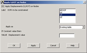
Select
...
UX
...
for
...
DOFs
...
to
...
be
...
constrained.
...
You
...
can
...
leave
...
the
...
Displacement
...
value
...
blank
...
since
...
the
...
default
...
is
...
zero.
...
Click
...
OK.
...
You'll
...
see
...
an
...
arrow
...
symbol
...
in
...
the
...
Graphics
...
window
...
indicating
...
that
...
the
...
node
...
A
...
is
...
constrained
...
in
...
the
...
radial
...
direction.
...
Select
...
Nodes
...
on
...
Face
...
1
...
ANSYS
...
provides
...
extensive
...
capabilities,
...
referred
...
to
...
as
...
"select
...
logic",
...
for
...
selecting
...
a
...
subset
...
of
...
the
...
full
...
model
...
using
...
various
...
criteria.
...
We'll
...
use
...
select
...
logic
...
to
...
select
...
the
...
nodes
...
on
...
face
...
1.
...
We'll
...
first
...
select
...
the
...
area
...
corresponding
...
to
...
face
...
1
...
and
...
then
...
select
...
the
...
nodes
...
attached
...
to
...
this
...
area.
...
Utility
...
Menu
...
>
...
Select
...
>
...
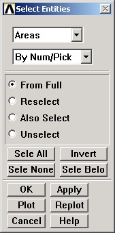
Entities
...
Select
...
Areas
...
from
...
the
...
pull-down
...
menu
...
at
...
the
...
top.
...
Make
...
sure
...
By
...
Num/Pick
...
is
...
selected
...
below
...
that.
...
Click
...
Apply.
...
Hold
...
down
...
the
...
left
...
mouse
...
button
...
until
...
face
...
1
...
is
...
picked.
...
Click
...
OK
...
in
...
the
...
pick
...
menu.
...
Only
...
the
...
area
...
corresponding
...
to
...
face
...
1
...
is
...
selected
...
currently.
...
Verify
...
this:
...
Utility
...
Menu
...
>
...
Plot
...
>
...
Areas.
...
Next
...
we'll
...
select
...
the
...
nodes
...
attached
...
to
...
the
...
selected
...
area.
...
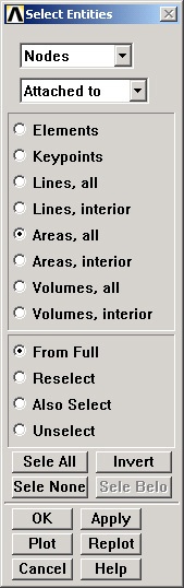
In
...
the
...
Select
...
Entities
...
menu,
...
select
...
Nodes
...
from
...
the
...
pull-down
...
menu
...
at
...
the
...
top
...
and
...
Attached
...
to
...
below
...
that.
...
Select
...
Areas,
...
All
...
below
...
that.
...
Click
...
Apply.
...
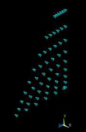
Check
...
that
...
only
...
nodes
...
attached
...
to
...
face
...
1
...
are
...
currently
...
selected:
...
Utility
...
Menu
...
>
...
Plot
...
>
...
Nodes
...
Apply
...
v=0
...
on
...
Face
...
1
...
Main
...
Menu
...
>
...
Preprocessor
...
>
...
Loads
...
>
...
Define
...
Loads
...
>
...
Apply
...
>
...
Structural
...
>
...
Displacement
...
>
...
On
...
Nodes
...
Pick
...
All
...
nodes
...
in
...
the
...
pick
...
menu.
...
Select
...
UY
...
for
...
DOFs
...
to
...
be
...
constrained
...
and
...
click
...
OK.
...
You'll
...
see
...
arrow
...
symbols
...
in
...
the
...
Graphics
...
window
...
indicating
...
that
...
the
...
nodes
...
on
...
face
...
1
...
are
...
constrained
...
in
...
the
...
circumferential
...
direction.
...
We can use Pick All since only the nodes on face 1 are currently selected. ANSYS commands apply only to the currently selected entities.
Select Nodes Along AB
Plot lines: Utility Menu > Plot > Lines
In the Select Entities menu, select Lines from the pull-down menu at the top and By Num/PickApply below that. Click OK.
Click on line AB (L7) and OK in the pick menu.
Next we'll select the nodes attached to the selected line. In the Select Entities menu, select Nodes from the pull-down menu at the top and Attached to below that. Select Lines, All below that. Click Apply.
Check that only nodes attached to line AB are currently selected: Utility Menu > Plot > Nodes
Apply w=0 Along AB
Main Menu > Preprocessor > Loads > Define Loads > Apply > Structural > Displacement > On Nodes
Pick All nodes in the pick menu. Select UZ for DOFs to be constrained and click OK.
Define Function
Recall that the BCs for face 2 are:
v=0.0001(rc-r) at all face 2 nodes
w=0 along CD (line L5)
Since the BC on v is a function of the spatial coordinates, we need to define a function to apply this BC. Bring up the function editor:
Utility Menu > Parameters > Functions > Define/Edit...
You can enter the function using the calculator buttons or type it in. The variables such as TIME, X, Y etc. that are available for defining functions are in the pull-down list below the Result field. For entering the spatial coordinates X and Y, use the pull-down menu. Enter the function:

Note that variables are enclosed in squiggly brackets.
Save the function: Function Editor > File > Save
Use vface2.func for the filename.
Close the function editor.
Define Table from Function
ANSYS doesn't allow the user to use functions directly while applying loads to a model. Instead, one has to go through the additional step of using a "Function Loader" that retrieves the function and loads it as a Table array. The Table array can then be applied to the model. The process is not exactly elegant but then we are engineers.
Utility Menu > Parameters > Functions > Read From File
Select vface2.func and click Open.
Enter vface2 for Table parameter name.
Observe that ANSYS displays the equation that will be used in creating the Table array. Click OK.
Select Nodes on Face 2
Start by selecting the whole model to undo previous selects.
Utility Menu > Select > Everything
Utility Menu > Plot > Areas
To select the nodes on face 2, we'll follow the same procedure as for face 1.
Utility Menu > Select > Entities
Select Areas from the pull-down menu at the top. Select By Num/Pick below that. Click Apply.
Hold down the left mouse button until face 2 is picked. Click OK in the pick menu.
Only the area corresponding to face 2 is selected currently. Verify this: Utility Menu > Plot > Areas.
Next we'll select the nodes attached to the selected area. In the Select Entities menu, select Nodes from the pull-down menu at the top and Attached to below that. Select Areas, All below that. Click Apply.
Check that only nodes attached to face 2 are currently selected: Utility Menu > Plot > Nodes
Apply BC for v on Face 2
We'll use the vface2 table that we created to apply this BC.
Main Menu > Preprocessor > Loads > Define Loads > Apply > Structural > Displacement > On Nodes
Pick All nodes in the pick menu. Select UY for DOFs to be constrained. Select Existing table under Apply as and click OK.
We have defined only one table (VFACE2) and that is automatically selected. Click OK.
You'll see arrow symbols in the Graphics window indicating that the nodes on face 2 are constrained in the circumferential direction.
Select Nodes Along CD
Plot lines: Utility Menu > Plot > Lines
In the Select Entities menu, select Lines from the pull-down menu at the top and By Num/Pick below that. Click Apply.
Click on line CD (L5) and OK in the pick menu.
Next we'll select the nodes attached to the selected line. In the Select Entities menu, select Nodes from the pull-down menu at the top and Attached to below that. Select Lines, All below that. Click Apply.
Check that only nodes attached to line CD are currently selected: Utility Menu > Plot > Nodes
Apply w=0 Along CD
Main Menu > Preprocessor > Loads > Define Loads > Apply > Structural > Displacement > On Nodes
Pick All nodes in the pick menu. Select UZ for DOFs to be constrained. Select Constant value under Apply as and click OK.
Utility Menu > Select > Everything
Utility Menu > Plot > Volumes
Save your work:Toolbar > SAVE_DB