 Sign-up for free online course on ANSYS simulations!
...
Enter the following parameters, clicking Accept after each. Check the figure of the geometry to see what dimension each parameter corresponds to.
R1=44e-3
R2=R1+88e-3
Z1=65e-3
Z2=14e-3
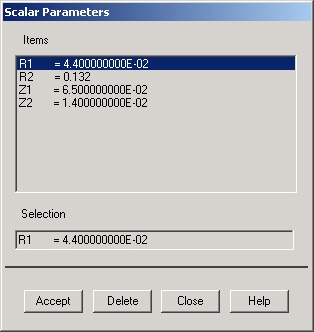
Click Close.
Switch to Cylindrical Coordinate System
...
When the active coordinate system is set to cylindrical, X, Y, and Z in the menus refer to the cylindrical coordinates r, θ (in degrees) and z, respectively. Remember to make this mental substitution as you enter the keypoint coordinates. Also, you can use the tab key to move the cursor to the next entry field. Don't forget to change the keypoint number as you enter the coordinates of the keypoints.
...
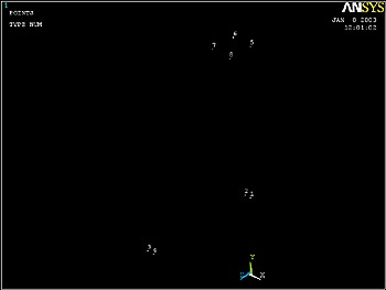
Enter the keypoint locations (think about where each one lies as you enter its coordinates):
Keypoint 1: X=R1, Y=90, Z=0, Click Apply.
Keypoint 2: X=R1, Y=95, Z=0, Click Apply.
Keypoint 3: X=R1, Y=95, Z=Z1, Click Apply.
Keypoint 4: X=R1, Y=90, Z=Z1, Click Apply.
Keypoint 5: X=R2, Y=90, Z=0, Click Apply.
Keypoint 6: X=R2, Y=95, Z=0, Click Apply.
Keypoint 7: X=R2, Y=95, Z=Z2, Click Apply.
Keypoint 8: X=R2, Y=90, Z=Z2, Click OK.
Save your work: Toolbar > SAVE_DB
Then click on the isometric view button  on the right toolbar.
Note the orientation of the x-y-z triad at the bottom in the isometric view. The Pan-Zoom-Rotate menu, as the name indicates, can be used to change the viewing direction, zoom in and out and rotate the model. Close this menu.
...
| newwindow | ||||
|---|---|---|---|---|
| ||||
https://confluence.cornell.edu/download/attachments/90093093/cross+section+geometry.jpg?version=1 |
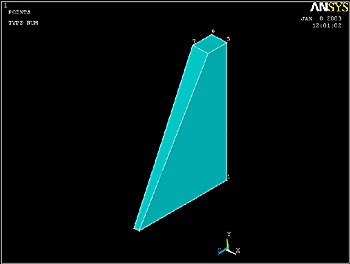
Create Volume
We'll next generate a volume from the 8 keypoints. The order of the keypoints should be around the bottom first and then the top.
...
Utility Menu > WorkPlane > Change Active CS to > Global Cartesian
ANSYS reports "csys=0" at the top of the Graphics window.
The lines (i.e. edges) connecting the keypoints that ANSYS generates during the volume creation are "straight" in the active coordinate system. Since we want these edges to be straight, the active coordinate system needs to be Cartesian rather than a curvilinear system like the Cylindrical.
...
Pick the 8 keypoints in the order in which they are numbered. Click OK in the pick menu.
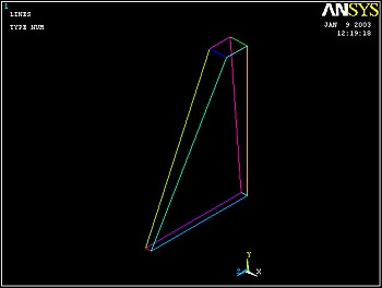
Plot Lines
...
Utility Menu > Plot > Lines
Turn off the background (otherwise it looks like the line connecting keypoints 7 and 8 is missing):
Utility Menu > PlotCtrls > Style > Background > Display Picture Background
Save Your Work
Toolbar > SAVE_DB
See and rate the complete Learning Module
...