 Sign-up for free online course on ANSYS simulations!
...
| Note |
|---|
For users of ANSYS 15.0, please check this link for procedures for turning on the Auto Constraint feature before creating sketches in DesignModeler. |
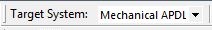
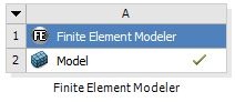
In the FE Modeler you will see the Import Summary, where a few basic model statistics are shown. Right above the Import Summary you will see Target System. The Target System should be set to Mechanical APDL because this is the code that ANSYS uses.
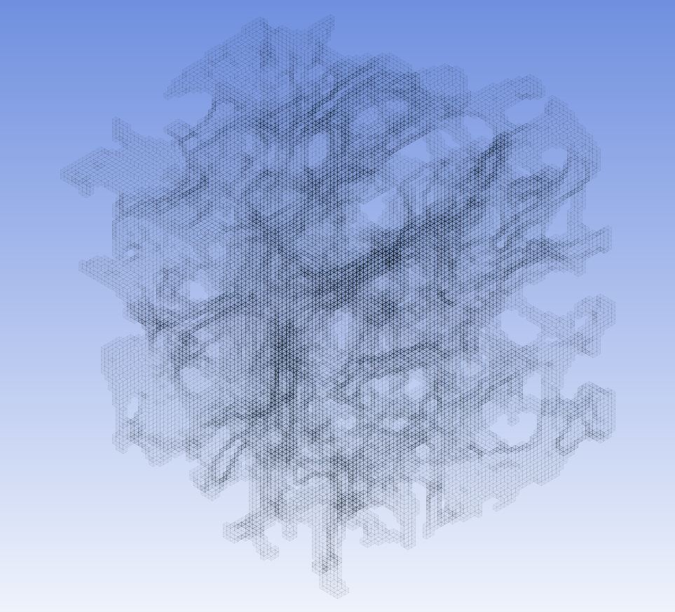
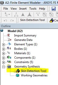
In the Outline window, highlight Skin Detection Tool . You will see a faint mesh of the Abaqus model.
Drag Static Structural into the Project Schematic page, right next to Finite Element Modeler, like so;
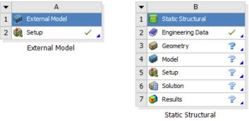
In the Project Schematic page, click and drag Setup from the External Model and drop it onto Model in Static Structural.
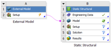
This will load the External Model into ANSYS Mechanical. When External Model is linked with Model in Static Structural, the mesh in the External Modeler is transfer to Mechanical and the user can proceed straight to setting up the physics.
Notice there is a lighting bolt symbol on the External Model. Right click on Setup and select Update.
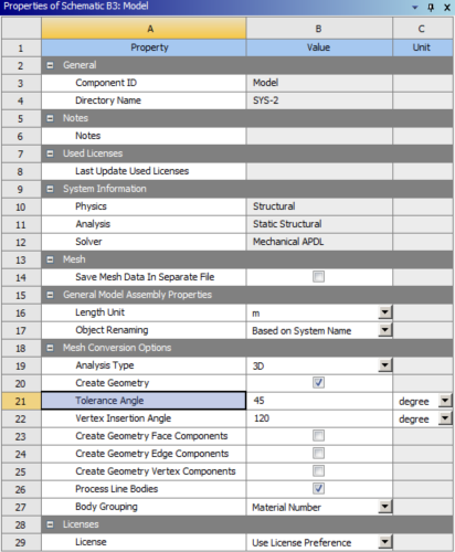
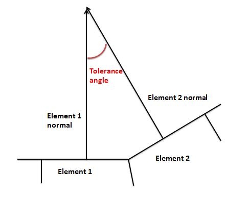
Under Static Structural, right click on Model > Properties. In Details View for Skin Detection Tool, The Tolerance Angle is set to 15 45 . The Skin Detection Tool Mesh Conversion process computes the angle between the normals of two adjacent elements in the mesh. If this angle is less than or equal to the Tolerance Angle then the two elements are in the same component, otherwise, they are separated. We will keep set the tolerance angle to 15 degrees.
In the Outline window, right click on Geometry Synthesis > Insert > Initial Geometry . This will reproduce the model in Workbench compatible format.
| Info | ||
|---|---|---|
| ||
The process of initializing this geometry takes up a lot of memory and computational time. It is best to leave the computer along to prevent freezing. The geometry should be generated in about 25 minutes. |
You should see a green check mark after the geometry has been generated.
For this particular mesh, the changing the tolerance angle does not affect solution results. For larger scale meshes, changing the tolerance angle of the mesh will have an affect on solution results.
You may now move on to the next step
...