 Sign-up for free online course on ANSYS simulations!
| Include Page | ||||
|---|---|---|---|---|
|
| Include Page | (Tutorial Name) - Panel | (Tutorial Name) - Panel |
|---|
(Tutorial Name)
Created using ANSYS (Version Number)
Learning Goals
In this tutorial, you will learn to:
- (e.g.: Determine the displacements and stresses in a bike crank using 3D FEA capabilities in ANSYS Mechanical)
- (e.g.: Verify the finite-element results from ANSYS by refining the mesh and also comparing with hand calculations)
| Note |
|---|
Under Construction |
Problem Specification
| Note |
|---|
Under Construction |
|
ANSYS AIM Forces in Permanent Magnets
Created using ANSYS AIM 18.2
Problem Specification
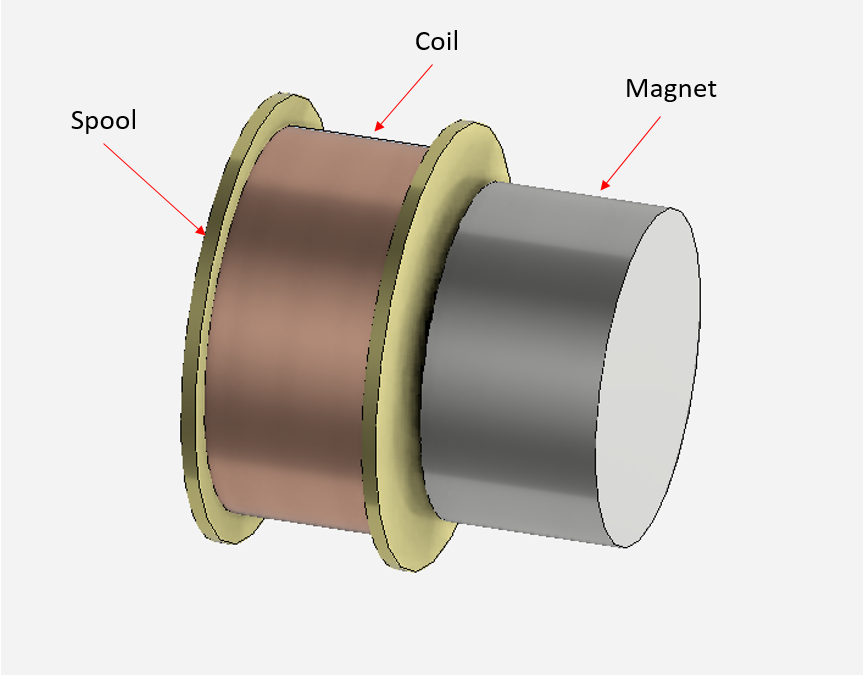
This problem is intended to address the questions of force calculations as well as modeling of permanent magnets in asymmetric and three dimensional geometries.The spool is made out of brass, the coil is made out of copper and the magnet is made of NdFe30 (Neodymium Iron). In this demonstration, two cases will be considered and the force between the magnet and the coil will be determined.
f = f(i,R,s)
where
f = force between magnet and coil i = current, R = horizontal displacement s = vertical displacement
In case one, both s = 0 and R = 0.254mm are held constant. Therefore, f = f(i)
In case two, s = 0mm and i = 50mA are kept constant. Therefore f = f(R)
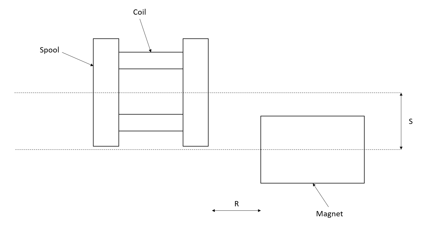
In the first case, the current will vary from from 0-100mA in 10mA intervals. In case two, the axial displacement will vary from 0.0-.5mm in 0.05mm intervals.
Go to Step 1: Pre-Analysis & Start-Up
Go to all ( ANSYS or FLUENT) AIM Learning Modules