 Sign-up for free online course on ANSYS simulations!
...
Creating the Geometry for the Bolted Nozzle Flange
Created using ANSYS 16.2
| Info |
|---|
The full Bolted Nozzle Flange module can be accessed on edx.org here. (Registration is required) |
Learning Goals
In this tutorial, you will learn how to create the geometry used for the Bolted Nozzle Flange problem presented in Module 3 of the Cornell's Engineering Simulations MOOC on edx.org.
...
| HTML |
|---|
<iframe width="640" height="360" src="//www.youtube.com/embed/i0jKSZvWY-8" frameborder="0" allowfullscreen></iframe> |
Note: selecting the correct edges
Selecting the correct edges for the Blends can be hard.
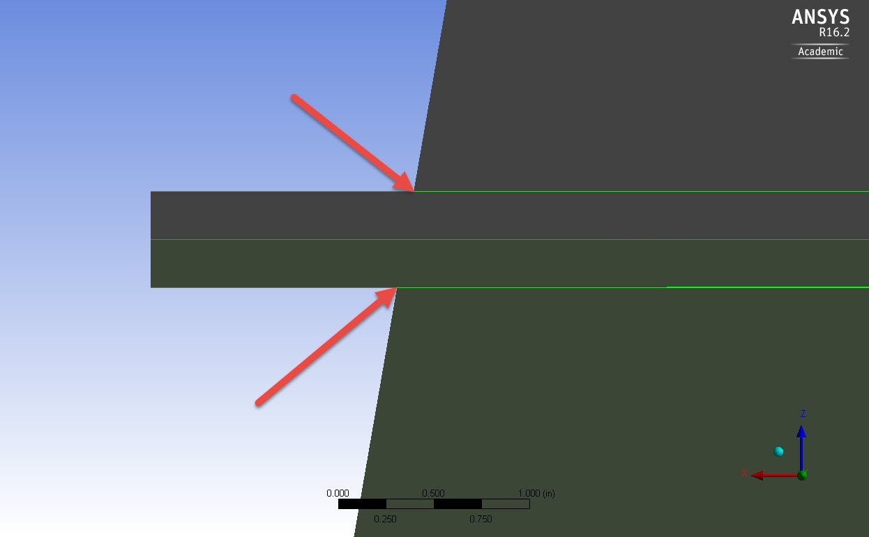
For the first blend, you need to select the circular edges around the nozzle; the ones right at the corner between the nozzle itself and the flange. Check the following picture from a side view of the geometry.
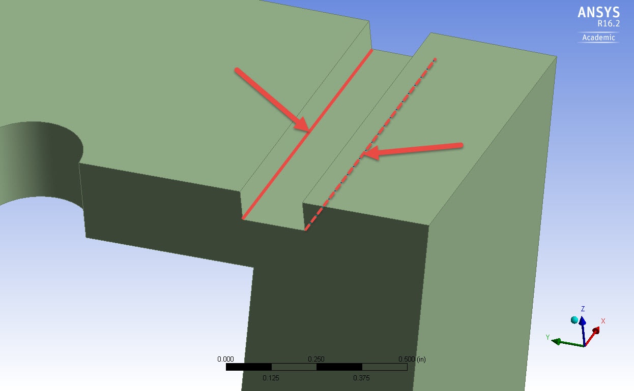
For the second blend, you need to select the bottom edges inside the groove. In the picture below you can see them highlighted, but note that to ease the understanding, a "sliced" geometry is shown. Your geometry will look like this by the end of the above video!
Specifying the Contact Regions
| HTML |
|---|
<iframe width="640" height="360" src="//www.youtube.com/embed/iECqzjMNnss" frameborder="0" allowfullscreen></iframe> |
Go to Step 1: Pre-Analysis & Start-Up
Go to all ( ANSYS or FLUENT) Learning Modules