| Include Page |
|---|
| SIMULATION: ANSYS Google AnalyticsSIMULATION: |
|---|
| ANSYS Google Analytics |
|---|
|
| Include Page |
|---|
| SIMULATION: 2D Steady Conduction - PanelSIMULATION: |
|---|
| 2D Steady Conduction - Panel |
|---|
|
...
ANSYS Mechanical is the application where we'll generate a mesh, apply the material properties and boundary conditions, and obtain a numerical solution to our boundary value problem. In order to start ANSYS Mechanical (Double Click) Model,  . When Mechanical opens, make sure that the units are properly defined to be in metric. Do this by clicking on Units, in the top toolbar, and selecting Metric (m, kg, N, s, V, A).
Create a Regular Mesh
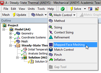
We will create a nice, regular mesh which is done using the "mapped face meshing" option. A mapped face mesh is a mesh that can be mapped to a rectangular domain, hence the name. Our domain is already rectangular, thus mapped faced meshing will yield a rectangular grid as the mesh.
First (Click) Mesh,  in the model tree. Next, (Click) Mesh Control > Mapped Face Meshing, as shown below.
| newwindow |
|---|
| Click Here for Higher Resolution |
|---|
| Click Here for Higher Resolution |
|---|
|
https://confluence.cornell.edu/download/attachments/146918513/MFM_Full.png |
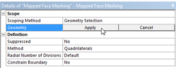
Then, click on the rectangle and it should be highlighted in green. If it does not highlight in green, click on the face selection filter button,

at the top of the GUI,then click on the rectangle. Once the rectangle has been selected,
(Click) Apply in the "Details of Mapped Face Meshing" table as shown below.
| newwindow |
|---|
| Click Here for Higher Resolution |
|---|
| Click Here for Higher Resolution |
|---|
|
https://confluence.cornell.edu/download/attachments/146918513/DMFM_Full.png |
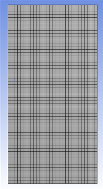
ANSYS now knows that a mapped face mesh has to be generated for the rectangle. Next,
(Click) Update,

, in order to generate the mesh. You should obtain the following mesh.
| newwindow |
|---|
| Click Here for Higher Resolution |
|---|
| Click Here for Higher Resolution |
|---|
|
https://confluence.cornell.edu/download/attachments/146918513/GenMesh_Full.png |
...
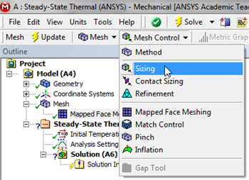
Let's specify the number of divisions to be used along each edge rather than have ANSYS pick them automatically. ANSYS calls this step "edge sizing". We will use 20 divisions along the vertical edges and 10 divisions along the horizontal edges. We will work with the horizontal edge first. In order to implement the edge sizing, first (Click) Mesh, . Next, (Click) Mesh Control > Sizing, as shown below.
| newwindow |
|---|
| Click Here for Higher Resolution |
|---|
| Click Here for Higher Resolution |
|---|
|
https://confluence.cornell.edu/download/attachments/146918513/InsSizing_Full.png |
Next, click on the edge selection filter,

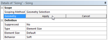
, located at the top of the GUI. Then click on the bottom edge of the rectangle, ctrl-click on the top of the rectangle (to select both of them), and
(Click) Apply in the "Details of Sizing" table as shown below.
| newwindow |
|---|
| Click Here for Higher Resolution |
|---|
| Click Here for Higher Resolution |
|---|
|
https://confluence.cornell.edu/download/attachments/146918513/DetSizing_Full.png |
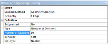
Next, set
Type to
Number of Divisions and set
Number of Divisions to 10, as shown below.
| newwindow |
|---|
| Click Here for Higher Resolution |
|---|
| Click Here for Higher Resolution |
|---|
|
https://confluence.cornell.edu/download/attachments/146918513/detdet_full.png |
You will notice that under Number of Divisions there is a row labeled Behavior which is defaulted to Soft. Change this option to Hard. Soft Behavior means that the mesher will take your sizing just as a guideline, not an absolute law. For our simple geometry, we know exactly what the mesh should look like, and don't want the mesher taking any creative interpretations of our sizing options.
This completes the sizing for the horizontal edge. Now, create a new edge sizing, apply it to the right and left vertical edges (ctrl-click to keep both of them selected.) And set the Number of Divisions to 20. After, you have properly implemented the two edge sizing commands, (Click) Update, , in order to generate the new mesh. You should then obtain the following mesh. Important note: If ANSYS modifies the number of divisions you give it, change the setting for Behavior in the above menu from Soft to Hard.
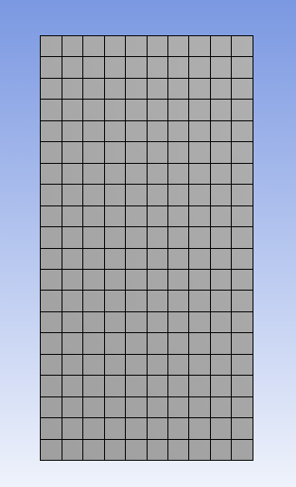
This completes the meshing process for this problem.
...
 Sign-up for free online course on ANSYS simulations!