 Sign-up for free online course on ANSYS simulations!
...
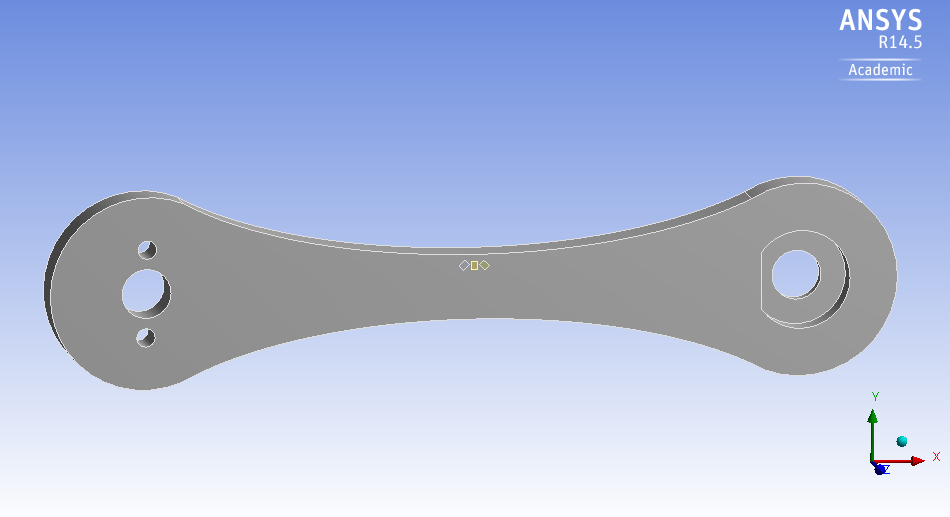
Consider adding a strain rosette to the ANSYS bike crank model, from the previous bike crank tutorial, to predict the strain that would be measured by a rosette mounted on the crank model. The rosette is placed along the top edge on the front face of the crank, midway between the support hole and the loaded hole as shown below.
The specifications of the rosettes are shown below.
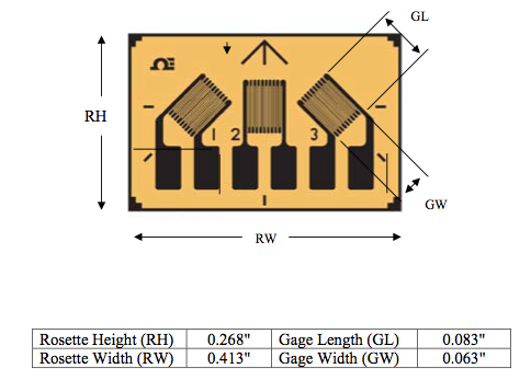
...
location of the gauge centers with respect to a coordinate system centered at the front face of the support hole is as follow:
Left Gauge: (3.244 in, 0.219 in)
Middle Gauge: (3.346 in, 0.219 in)
Right Gauge: (3.448 in, 0.219 in)
The rosette has the following characteristics.
Go to Step 1: Pre-Analysis & Start-Up
...