| Include Page |
|---|
...
|
...
|
| Include Page |
|---|
...
|
...
|
Numerical Results
Here, we find the strain of each surface bodies along their lengths. We do this using the local coordinate system of each gauge which is given to us from the elemental triad solution.
| HTML |
|---|
<iframe width="600" height="338" src="//www.youtube.com/embed/v2zak9T5lLA?rel=0" frameborder="0" allowfullscreen></iframe> |
Summary of steps in the above video:
- Right click on Solution the tree > Strain > Normal
- For geometry > select leftmost strain body > Apply
- For Orientation > x axis (can look at elemental triad system)
- Change Global System to Solution System
- Right Click Solution > Evaluate All Results
| Note | |
|---|---|
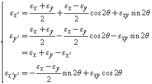
| Wiki Markup | The video mentions that you need to pay attention to the sign of the strain value only, not the direction of the coordinate system. For example, you should not beyou should not be concerned, if say, the x-direction for one of your gauge points in the opposite direction of the other two gauges in the rosette. This is because the strain transformation is invariant when you rotate a coordinate direction by 180 deg. The transformation formula, {menulink:custom|link=http://www.efunda.com/formulae/solid_mechanics/mat_mechanics/plane_strain.cfm#Transform|target=_blank}see this link{menulink}, has cos(2*theta) and sin(2*theta). When theta = 180 deg, cos(2*theta) and sin(2*theta) will be the same as when theta = 0. formula, shown below, has cos(2θ) and sin(2θ). When θ = 180 deg, cos(2θ) and sin(2θ) will be the same as when θ = 0. For more information on transformations, see this link. |
Go to Step 7: Verification & Validation
...
 Sign-up for free online course on ANSYS simulations!