 Sign-up for free online course on ANSYS simulations!
| Include Page |
|---|
...
|
...
|
| Include Page |
|---|
...
|
...
|
Bike Crank: Part 2
Created using ANSYS 14.5
| Note |
|---|
This tutorial has videos. If you are in a computer lab, make sure to have head phones. |
Learning Goals
In this tutorial, you will learn to:
- Determine the strain values that would be measured by a strain rosette mounted on the bike crank.
- Verify the finite-element results from ANSYS by comparing it with hand calculations (using Euler-Bernoulli beam theory).
Problem Specification
Consider adding a strain rosette to the ANSYS bike crank model , from the previous bike crank tutorial, to predict the strain that would be measured by a rosette mounted on the crank model. The rosette is placed along the top edge on the front face of the crank, midway between the support hole and the loaded hole as shown below.
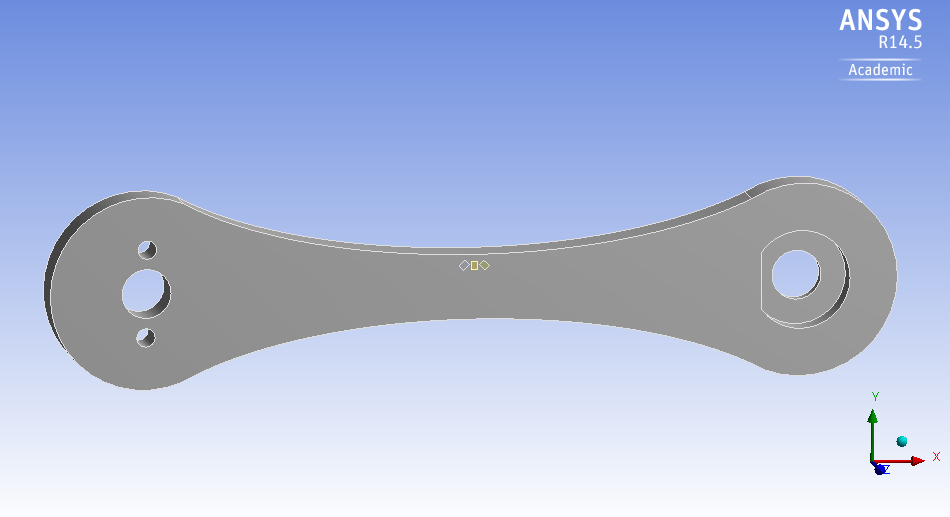
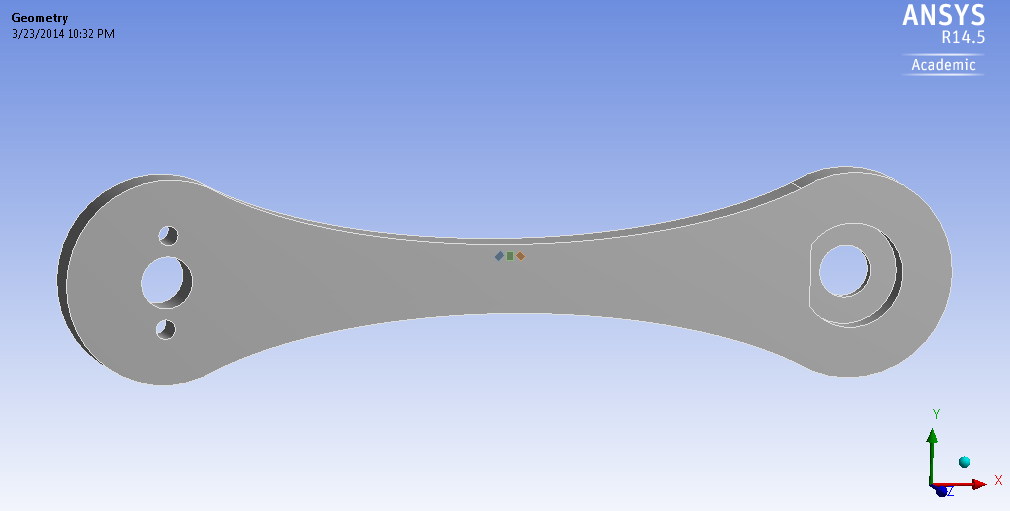
The location of the gauge centers with respect to a coordinate system centered at the front face of the support hole is as followfollows:
Left Gauge: (3.244 in, 0.219 in)
...
Right Gauge: (3.448 in, 0.219 in)
The rosette has the following characteristicsdimensions are shown in the figure below.
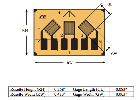
Determine the strain value that would be measured by each gauge on the rosette. Each gauge measures the extensional strain along its length (the longer dimension).
Go to Step 1: Pre-Analysis & Start-Up
...