 Sign-up for free online course on ANSYS simulations!
| Include Page | ||||
|---|---|---|---|---|
|
This tip will use the Tensile Bar tutorial to demonstrate fatigue analysis in Mechanical. It is recommended to become familiar with the tensile bar tutorial before you proceed. Please download the workbench model here.
Please also see related discussion in this document.
Procedure
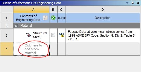
The provided workbench file already has the solution for the problem. We will create another material and assign Alternating Stress Mean Stress and re-run the simulation. Restore the downloaded archive and double click on Engineering Data. In Engineering Data, click on the blank box and enter Al 6061-T6 to create a new material.
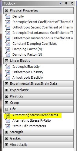
Once the new material is created, expand Life from the toolbox and double Structural Steel and click on Alternating Stress Mean Stress.
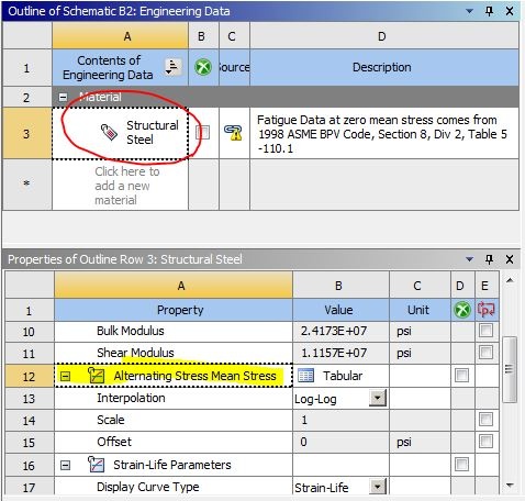
Change the Interpolation to Semi-Log.
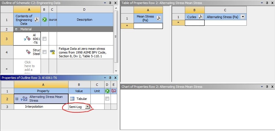
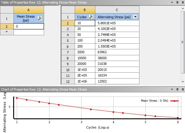
Enter 0 for the Mean Stress and the following data for cycles and alternating stress for aluminum.
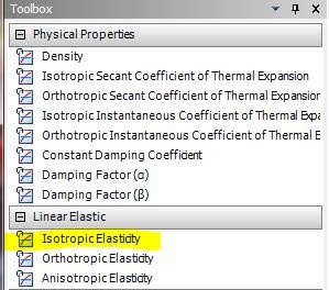
From the toolbox, double click on Isotropic Elasticity.
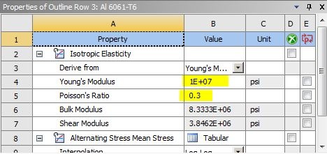
Enter 1e7 psi for Young's Modulus and 0.3 for Poisson's Ratio. You can change the units from the Units tab on the top tool bar.
The window on the right shows tabulated alternating stress for steel and its mean stress.
| Info | ||
|---|---|---|
| ||
If you wish to use a new material to perform fatigue analysis, you must enter its alternating stresses at specific cycles before you specify its isotropic properties. The data for alternating stresses for various materials can be found in most strength of materials textbooks. |
Verify that the Tensile Ultimate Strength is specified:

Click on Return to Project.

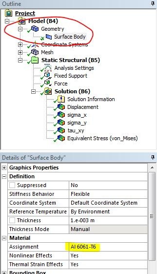
Double click on Model and select Yes when promptedto launch ANSYS Mechanical. The boundary conditions and solution have already been setup . From the tree, expand Geometry and select Surface Body. Notice the model in the main window is now highlighted. Change the material assignment to Al 6061-T6.
Right click on Solution and insert Fatigue Tool.
...
and the solution is provided.
Right click on Solution and insert Fatigue Tool.

Highlight Fatigue Tool and select Goodman for Mean Stress Theory.

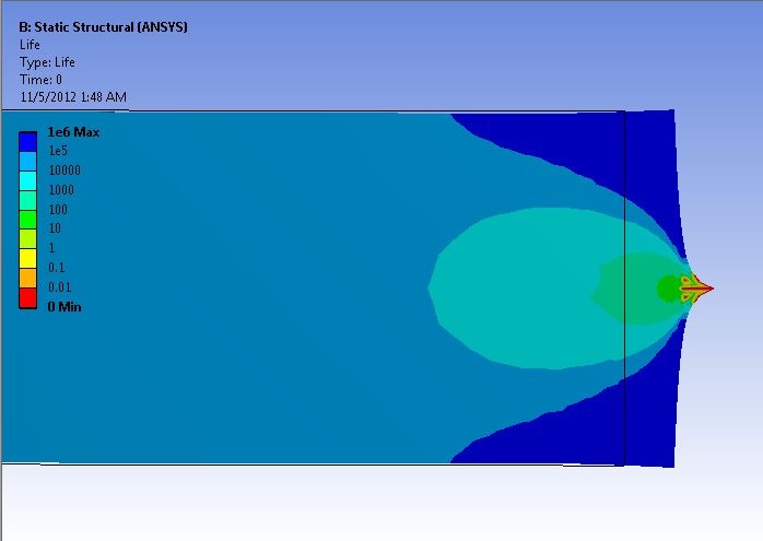
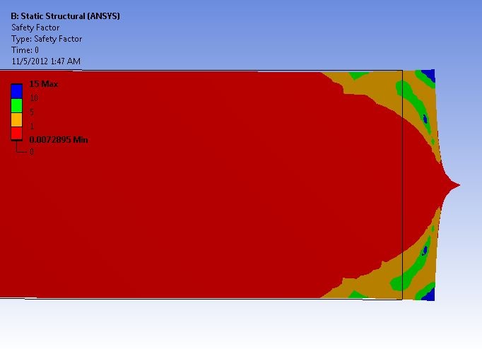
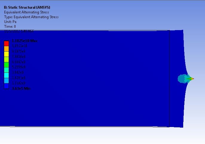
There are a number of options from the fatigue tool you can choose to include in the analysis, choose them accordingly. For demonstration, only life, safety factor, and alternating stress will be evaluated. Right click on Fatigue tool and insert Life, Safety Factor, and Equivalent Alternating Stress.
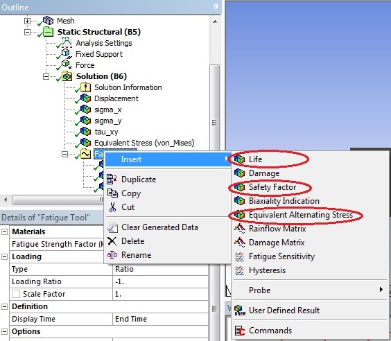
Click on Solve to generate new results. Zoom in on the right side of the bar by right click and drag. The fatigue analysis of a tensile bar subjected to a point load is shown below:
| Note |
|---|
Specifying the loading ratio to get a loading scheme in ANSYSConsider the case where the load varies smoothly between 500N and -1000N on each cycle. You first perform static loading at -1000N. For the fatigue portion, you must specify the loading ratio in the Fatigue tool (under "Loading Type", select "Ratio") to let ANSYS know what your load cycle will be. This is where ANSYS will know the ratio of your loading scheme (which is varying from 500N to -1000N). This value should be set to -0.5. The resulting sinusoidal graph produced on the right, should vary from an amplitude of 1 to -0.5. ANSYS uses the -1000N in the static loading as a starting point. What this means in ANSYS is that the static loading boundary condition of -1000N is going to be applied as the "max" (ie -1000*1 = -1000N) and then for the "min" it will be 500N (ie -1000*-0.5 =500N). |