 Sign-up for free online course on ANSYS simulations!
...
| Include Page | ||||
|---|---|---|---|---|
|
Optimization
Set-Up of
...
Optimization
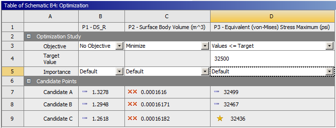
Begin this step, by double clicking on Optimization. At this point, ANSYS must be told that the objective function(volume) is to be minimized while staying below the 32.5 KSI Von Mises stress threshold. Under, the "Table of Schematic B4: Optimization" change the Objective of Surface Body Volume to Minimize. Next, change the Objective of Equivalent Stress Maximum to Values <= Target. Then, set the Target Value of Equivalent Stress Maximum equal to 32,500 PSI. Now, execute the optimization by clicking Update Optimization. The optimization should yield the results shown, below. 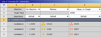
| newwindow | ||||
|---|---|---|---|---|
| ||||
https://confluence.cornell.edu/download/attachments/131466109/ResultsRoundOne_Full.png |
Modifying The Priority of The Constraints
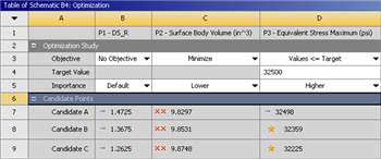
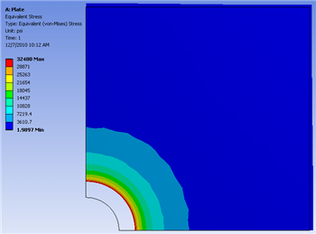
The results from the first execution of the optimization all of equivalent Von Mises stresses that exceed the 32.5 KSI threshold. The minimization of the volume is less important than staying below the equivalent Von Mises stress. In order to emphasize the priority of the Von Mises stress criterion set the Importance of Equivalent Stress Maximum to Higher and set the Importance of Surface Body Volume to Lower. Click Update Optimization to re-run the optimization with the new criteria. You should obtain the results shown below. Notice, that now the Von Mises stress threshold is not exceeded.
| newwindow | ||
|---|---|---|
| Click Here for Higher Resolution | Click Here for Higher Resolution | https://confluence.cornell.edu/download/attachments/131466109/OptResultsRoundTwo_Full.pngoptimization+results.PNG?version=1&modificationDate=1321903540000 |
Obtaining the Graphical Results
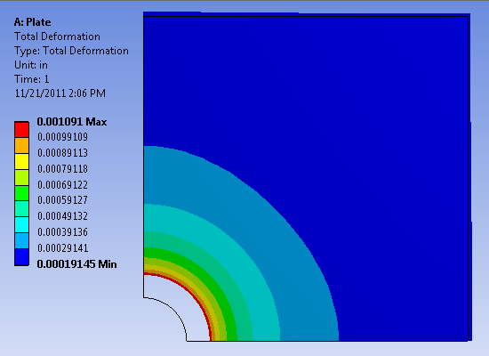
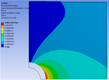
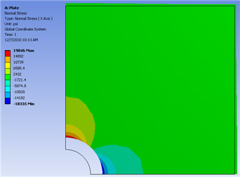
At this point the Candidate A results will be inputted back into the Design Modeler. That, is the radius from Candidate A will be set as the radius of the hole in Design Modeler. In order to do so, (Right Click) Candidate A > Insert as Design Points. Next, click Return to Project and double click on Parameter Set. In the "Table of Design Points" (Right Click) Current > Duplicate design point then (Right Click) DP1 > Copy Inputs to Current. In the previous commands you saved the previous current design point by moving it to DP2 and you have inserted Candidate A into the Current design point. Now, click Update All Design Points. Now, the radius of Candidate A has been inserted as the radius in the Design Modeler. Next, click Return to Project and double click Results. Now, the graphical results for the Candidate A radius of 1.4725 3278 inches can be viewed. The graphs below display the directional deformation, the equivalent Von Mises stress and the normal stress respectively.Directional
Total Deformation
...
| newwindow | ||||
|---|---|---|---|---|
| ||||
https://confluence.cornell.edu/download/attachments/131466109/DirecDef_RoundTwo_InitMesh_Full.pngoptimized+total+deformation.PNG?version=1&modificationDate=1321903689000 |
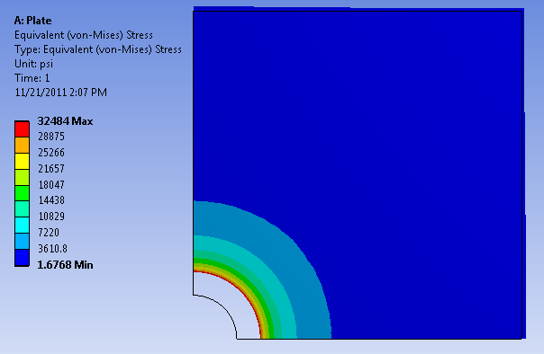
Equivalent Von Mises Stress
| newwindow | ||||
|---|---|---|---|---|
| ||||
https://confluence.cornell.edu/download/attachments/131466109/EquivStress_RoundTwo_InitMesh_Full.png |
| newwindow | ||
|---|---|---|
| Click Here for Higher Resolution | Click Here for Higher Resolution | https://confluence.cornell.edu/download/attachments/131466109/NormStress_RoundTwo_InitMesh_Full.png |
...