 Sign-up for free online course on ANSYS simulations!
...
Now, the properties of the fluid that is being modeled will be specified. The properties of the fluid were specified in the Problem Specification section. In order to create a new fluid (Click) Problem Setup > Materials > Fluid > Create/Edit... as shown in the image below.
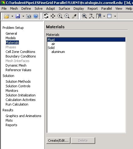
In the Create/Edit Materials menu set the Density to 1.331 kg/m^3 (constant) and set the Viscosity to 2.34e-05 kg/(ms) (constant) as shown in the image below.
...
In order to start the process (Click) Problem Setup > Boundary Conditions > inlet > Edit... as shown in the following image.
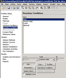
Note that the Boundary Condition Type should have been automatically set to velocity-inlet. Now, the velocity at the inlet will be specified. In the Velocity Inlet menu set the Velocity Specification Method to Magnitude, Normal to Boundary, set the Velocity Magnitude (m/s) to 6.58 m/s and set the Fluctuation Velocity Algorithm to Spectral Synthesizer (this is needed to fluctuate the velocity at the inlet). Also set the Turbulence Specification Method to Intensity and Hydraulic Diameter. Set the value of Turbulent Intensity (%) to 10 % and Hydraulic Diameter (m) to 0.0127 m. Finally set the Reynolds-Stress Specification Method to K or Turbulent Intensity as shown below. Click OK to close the Velocity Inlet menu. 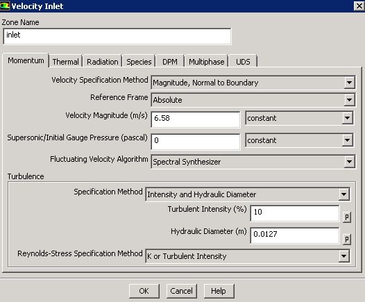
...
Outlet Boundary Condition
...
First, select outlet in the Boundary Conditions menu, as shown below. 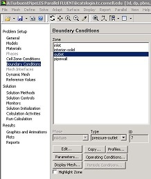 Higher Resolution Image
As can be seen in the image above the Type should have been automatically set to pressure-outlet. If the Type is not set to pressure-outlet, then set it to pressure-outlet. Now, no further changes are needed for the outlet boundary condition.