 Sign-up for free online course on ANSYS simulations!
...
Left click (and hold) on Fluid Flow (FLUENT), and drag the icon into the empty space in the Project Schematic. Your ANSYS window should now look comparable to the image below.
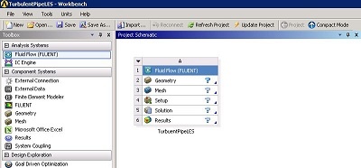
Rename the project to TurbulentPipeLES. We will work through each step from top down to obtain the solution to the problem.
Analysis Type
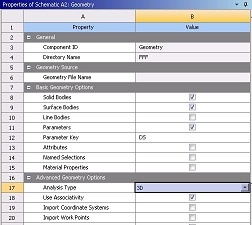
As noted earlier, the computational domain for this simulation will be a full 3-dimensional pipe. In the Project Schematic of the Workbench window, right click on Geometry and select Properties. The properties menu will then appear to the right of the Workbench window. Under Advance Geometry Options, make sure that the Analysis Type is 3D as shown in the image below.
Launch Design Modeler
In the Project Schematic, double click on Geometry to start preparing the geometry.
At this point, a new window, ANSYS Design Modeler will be opened. You will be asked to select desired length unit. Use the default meter unit and click OK.