 Sign-up for free online course on ANSYS simulations!
| Include Page | ||||
|---|---|---|---|---|
|
| Panel |
|---|
Author: Ranjith Tirunagari, Cornell University Problem Specification |
| Include Page | ||||
|---|---|---|---|---|
|
...
Mesh
In this section the geometry will be meshed using inflation feature to cluster more cells near the wall of the cylinder.
Launch Mesher
In order to begin the meshing process, go to the Workbench Project Page, then (Double Click) Mesh.
Inflation Feature (Mesh Control).
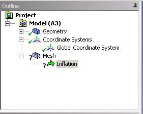
Right-click on the Mesh, in the Outline view, choose Insert and then choose Inflation.
Mesh> Insert> Inflation
The Outline view should look something similar to the figure below.
The parameters for the Inflation are given in the Details Pane. With Geometry highlighted, select the cylinder using body selection tool,  , and click Apply.
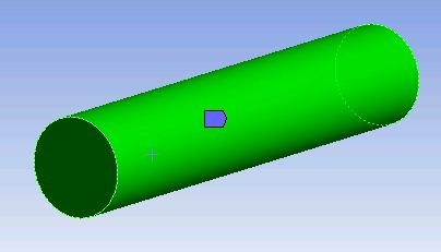
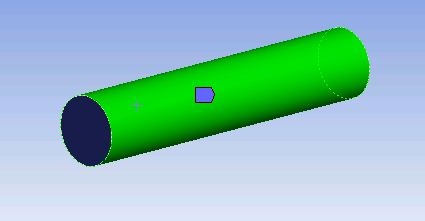
With Boundary highlighted, select the lateral surface using face selection tool,  , and click Apply.
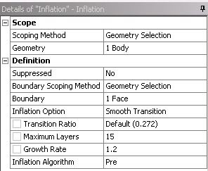
Finally, change Maximum Layers to 15 since we need more cells near the wall. The Details view should look something similar to the figure below.
Click on the Mesh in the Outline View to get the mesh details in the Details View. Under Sizing,change Use Advanced Size Function to Off, Relevance Center to Fine, element Size to 4e-04m, Smoothing to High,
Right-click Mesh and choose to Generate Mesh,  , to generate the mesh. The Details View should look something similar to:
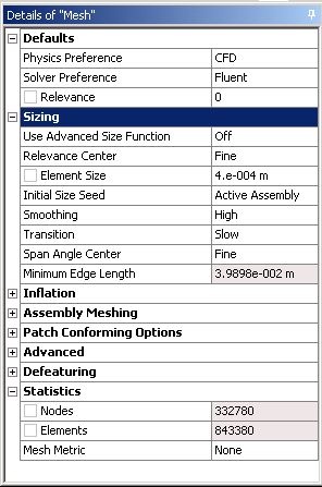
From the Mesh Statistics (in the figure above) we observe that we have about 0.85 million elements which would require multiple cores to run the simulation.
Create Named Selections
Here, the faces of the geometry will be given names so one can assign boundary conditions in Fluent in later steps. The left face of the pipe will be called "Inlet" and the right face will be called "Outlet". The lateral (or curved) surface of the pipe will be called "PipeWall".
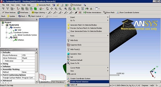
To name the left face select the face selection tool, , (Left) Click the appropriate face and then (Right) Click to select Create Named Selection.
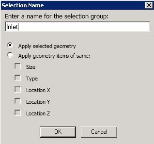
Enter Inlet in the Selection Name Box as shown in the figure.
Repeat the same procedure for the other two faces.
Save, Exit & Update
First save the project. Next, close the Mesher window. Then, go to the Workbench Project Page and click the Update Project button,  .
.
Go to Step 4 - : Physics Setup (Physics)