 Sign-up for free online course on ANSYS simulations!
...
| Note |
|---|
For users of ANSYS 15.0, please check this link for procedures for turning on the Auto Constraint feature before creating sketches in DesignModeler. |
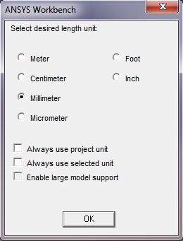
In project Project Schematic, double click on Geometry to open the Design Modeler. When prompted, select Milimeter Millimeter as the unit.
Click on the XY Plane and the z axis 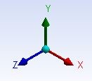 to begin sketching. Use the Line sketching tool to create a vertical line starting from the x axis . Hover the cursor around the axis until you see a symbol C to begin your sketch. The symbol C means the line is coincident with the x axis. Next, use the Arc by Center to create the dome of the shell. Hover the cursor near the y axis until you see the symbol C. Single click on the y axis and click again on the tip of the line you have just created. You should see a symbol P when you click on the vertex, which means coincident. Finally, click on the y axis again to finish the arc.
...
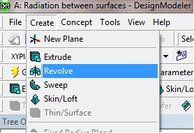
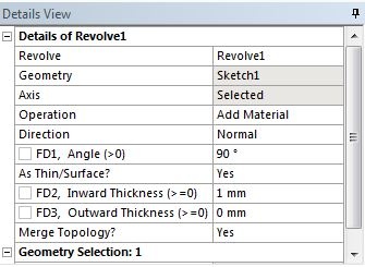
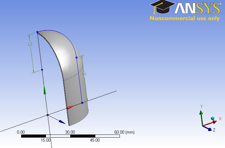
Click on Create from the top menu bar and select Revolve . The Revolve tool should automatically select your shell sketch for its geometry. If not, highlight the cell next to geometry and select Sketch1 under the XYPlane tree. Select the Y axis for Axis . This will allow the sketch to revolve around the y axis to create a shell. Change the Angle from 360 to 90 degrees. Highlight As Thin/Surface? and change the option from No to yes . Keep the Inward Thickness to 1 mm . Click on Generate .
The 1/8 shell model
Create the Specimen
...
Once everything is specified as above, click Generate. You should see 2 Parts, 2 Bodies in the Tree Outline. Your model should look like the following:
...