 Sign-up for free online course on ANSYS simulations!
...
| Note |
|---|
For users of ANSYS 15.0, please check this link for procedures for turning on the Auto Constraint feature before creating sketches in DesignModeler. |
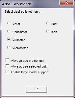
In project Project Schematic, double click on Geometry to open the Design Modeler. When prompted, select Milimeter Millimeter as the unit.
Click on the XY Plane and the z axis 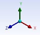 to begin sketching. Use the Line sketching tool to create a vertical line starting from the x axis . Hover the cursor around the axis until you see a symbol C to begin your sketch. The symbol C means the line is coincident with the x axis. Next, use the Arc by Center to create the dome of the shell. Hover the cursor near the y axis until you see the symbol C. Single click on the y axis and click again on the tip of the line you have just created. You should see a symbol P when you click on the vertex, which means coincident. Finally, click on the y axis again to finish the arc.
...
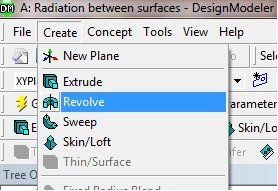
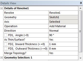
Click on Create from the top menu bar and select Revolve . The Revolve tool should automatically select your shell sketch for its geometry. If not, highlight the cell next to geometry and select Sketch1 under the XYPlane tree. Select the Y axis for Axis . This will allow the sketch to revolve around the y axis to create a shell. Change the Angle from 360 to 90 degrees. Highlight As Thin/Surface? and change the option from No to yes . Keep the Inward Thickness to 1 mm . Click on Generate .
The 1/8 shell model
Create the Specimen
...
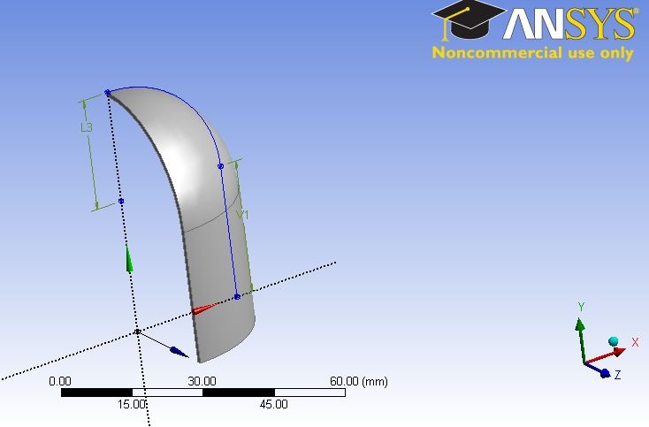
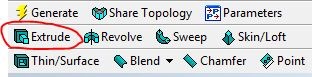
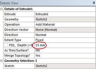
Click on the Extrude icon and select the quarter circle for the geometry. In the Details of Extrude1 window, set the Depth to 15 mm .
Once everything is specified as above, click Generate. You should see 2 Parts, 2 Bodies in the Tree Outline. Your model should look like the following:
...