 Sign-up for free online course on ANSYS simulations!
...
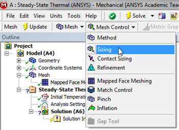
Let's specify the number of divisions to be used along each edge rather than have ANSYS pick them automatically. ANSYS calls this step "edge sizing". We will use 20 divisions along the vertical edges and 10 divisions along the horizontal edges. We will work with the horizontal edge first. In order to implement the edge sizing, first (Click) Mesh,  . Next, (Click) Mesh Control > Sizing, as shown below.
| newwindow | ||||
|---|---|---|---|---|
| ||||
https://confluence.cornell.edu/download/attachments/146918513/InsSizing_Full.png |
Next, click on the edge selection filter,
 , located at the top of the GUI. Then click on the bottom edge of the rectangle and (Click) Apply in the "Details of Sizing" table as shown below.
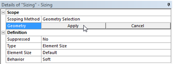
| newwindow | ||||
|---|---|---|---|---|
| ||||
https://confluence.cornell.edu/download/attachments/146918513/DetSizing_Full.png |
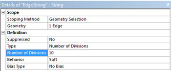
Next, set Type to Number of Divisions and set Number of Divisions to 10, as shown below.
| newwindow | ||||
|---|---|---|---|---|
| ||||
https://confluence.cornell.edu/download/attachments/146918513/detdet_full.png |
This completes the sizing for the horizontal edge. Now, create a new edge sizing, apply it to the right vertical edge and set the Number of Divisions to 20. After, you have properly implemented the two edge sizing commands, (Click) Update,
 , in order to generate the new mesh. You should then obtain the following mesh. Important note: If ANSYS modifies the number of divisions you give it, change the setting for Behavior in the above menu from Soft to Hard.
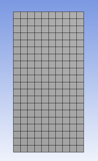
This completes the meshing process for this problem.
...