 Sign-up for free online course on ANSYS simulations!
| Include Page |
|---|
...
|
...
|
| Panel |
|---|
Author: Ben Mullen, Cornell University Problem Specification |
Setup (Physics)
Set Material Properties
Outer Surface
Because the thickness of the blade varies, we need to set the material via commands. First, we will create a command that governs the material properties of the outer surface of the blade. To create a command, right click on the Outer Surface surface body, and select Insert > Commands. In the command prompt, insert the following:
| Info |
|---|
/prep7 !Call the Preprocessor et,matid,181 !Specify the element type, shell 181 MP,EX,1,33E9 !Define Young's Modulus: X Direction MP,PRXY,1,0.3 !Define Major Poisson's ratio XY |
Spar
Create a command for the spar, and insert the following
| Info |
|---|
/prep7 !Call the Preprocessor et,matid,181 !Specify the element type, shell 181 MP,EX,2,101E9 !Define Young's Modulus: X Direction MP,PRXY,2,0.3 !Define Major Poisson's ratio XY |
Setup Varying Thickness function
Outer Surface
Now, we need to set up the varying thickness function governing the blade's thickness. To do this, we will need to open ANSYS APDL. To open, go to Start > All Programs > ANSYS 13.0 > Mechanical APDL (ANSYS). Once ANSYS APDL opens, go to Parameters > Functions > Define/Edit. The function that will drive the thickness is 0.030 - 0.00048485X where X is the distance from the origin along the X-axis. In the Result text box, type .03 - 0.00048485*, then, to input the x variable, open the drop down menu next that is defaulted to Time and change it to X.
...
Press ENTER. Then in the Function Editor window, go to File > Save. Change the Save as type to All Files, and name the file vth.txt. Once you save, you may close ANSYS APDL. Now, open the text file you just created. We need to name the function. In the text file, use Replace to replace all instances of %_FNCNAME% with vth. Also, we need to add the line
| Info |
|---|
sect,1,shell !Specify the section type |
to the end of the code. For simplicity, I have posted the entire code here:
| Info |
|---|
*DIM,vth,TABLE,6,5,1, !Dimension The Table for the Thickness Function ! Begin of equation: .030-{X}*.00048485 sect,1,shell !Specify the section type |
Post this code at the end of the command snippit you created for the Outer Surface.
Spar
We need to repeat the above step, creating a command for the spar, but this time the thickness will be constant at 0.20 m. We will also have to make minute changes to the code to refer to the correct section. For simplicity, the code is posted below. Copy and paste the code below into a command snippit for the Spar.
| Info |
|---|
/prep7 !Call the Preprocessor et,matid,181 !Specify the element type, shell 181 MP,EX,2,101E9 !Define Young's Modulus: X Direction MP,PRXY,2,0.3 !Define Major Poisson's ratio XY *DIM,sth,TABLE,6,5,1, !Dimension The Table for the Thickness Function ! Begin of equation: .020 sect,2,shell !Specify the section type |
...
https://confluence.cornell.edu/download/attachments/151192811/Command+Snippits+Large.png?version=1&modificationDate=1310690913000| Include Page | ||||
|---|---|---|---|---|
|
Physics Setup
| Note |
|---|
This tutorial is not being updated any more. We recommend that you follow this newer tutorial on fluid-structure analysis of a wind turbine blade. Thank you! |
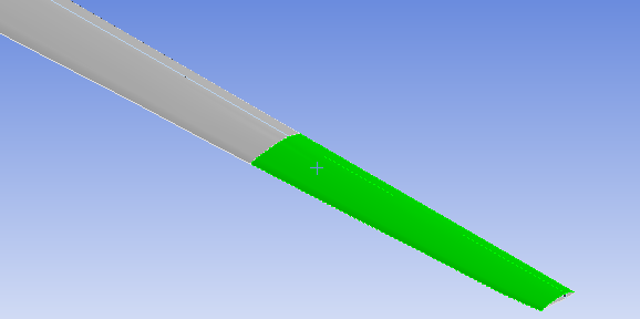
Varying Thickness
Right click on Geometry and insert Thickness. Hold down the control button and select the top and bottom surfaces of the wind blade.
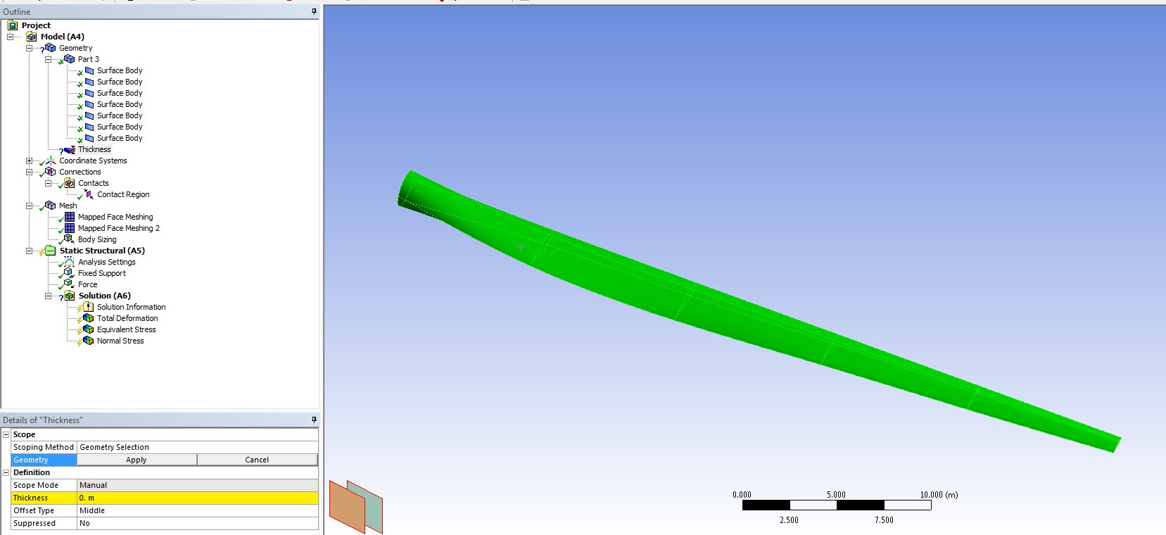
Select function from the drop down list in Thickness. Enter the thickness as a function of length: 0.03-0.00048485*x. The thickness graphics will be displayed:
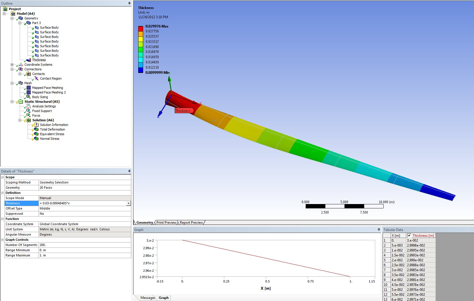
The thickness of the spar is 0.02 meters. Locate the appropriate surface bodies that represent the spar and change the thickness to 0.02 meters.

Connections
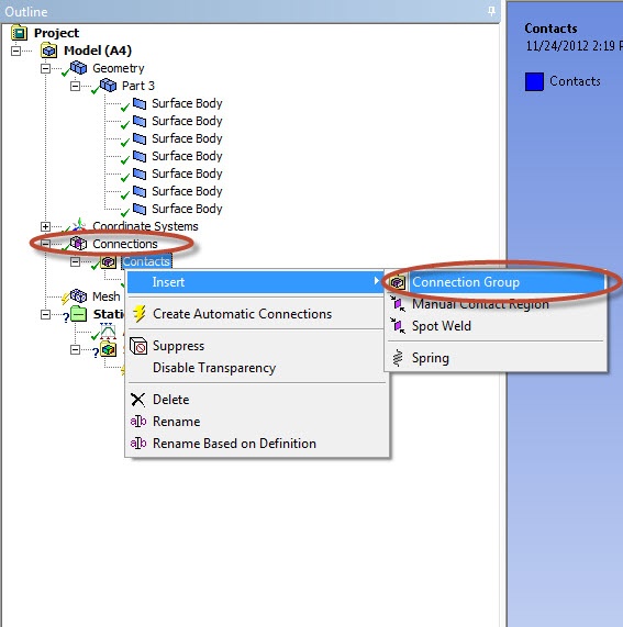
The contact between the wind blade and the spar needs to be modeled. Right click on Connections and insert a Connection Group.
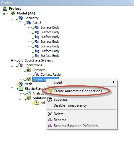
In the connection group named Contacts 2, change the Face/Face detection to No and Face/Edge detection to Yes.

Right click on Contacts 2 and click on Create Automatic Connections.
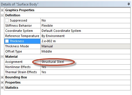
Material Properties
For each surface body, check that Structural Steel is assigned as the material.
Prevent ANSYS from changing Material Properties
We need to create one more command in order to ensure that ANSYS uses the varying thickness. In the Outline window, right click Static Structural (B5) and select Insert > Commands. Copy and paste the code below into the command window
...
Fixed Support
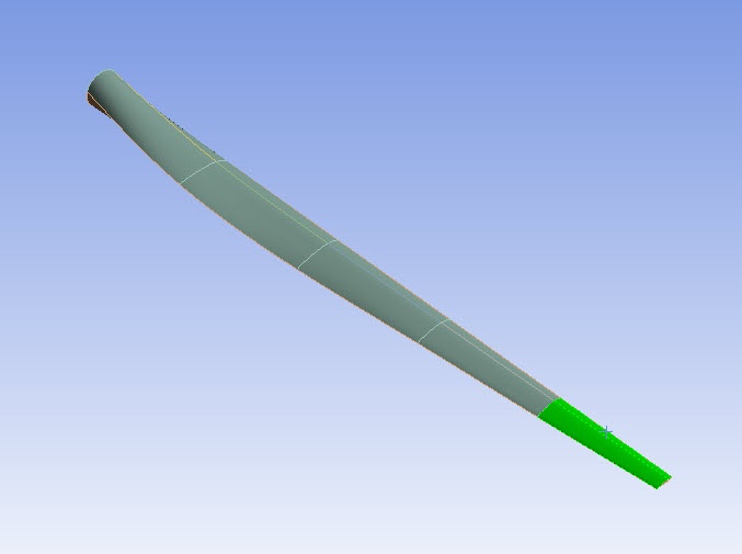
We will fix the ring at the end of the blade. To accomplish this, click on Static Structural (B5) to bring up the Environment menu bar. In the Environment menu bar, select Supports > Fixed Support. Next, make sure the edge selection filter  is selected. Hold Ctrl, and click on the 2 edges that make up the ring at the end shoulder of the blade (see image below).
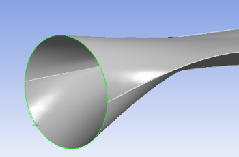
When both edges have been selected, press Geometry > Apply.
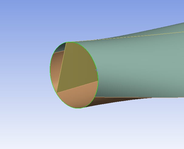
Force Load
We want to apply a 1000 N downward force on the blade. To initialize a force load, in the Environment menu bar select Loads > Force. Make sure the surface selection filter  is selected and choose the two upper surface of the end of blade, as shown in the image below.
When the surface have been selected, press Geometry > Apply in the Details window. Next, select Define By > Components. Define the Y Component as -1000 N.

We are now ready to set up the solution and solve.
Go to Step 5 - : Numerical Solution