 Sign-up for free online course on ANSYS simulations!
| Include Page | ||||
|---|---|---|---|---|
|
| Include Page | ||||
|---|---|---|---|---|
|
Physics Setup
| Note |
|---|
This tutorial is not being updated any more. We recommend that you follow this newer tutorial on fluid-structure analysis of a wind turbine blade. Thank you! |
Varying Thickness
Right click on Geometry and insert Thickness. Hold down the control button and select the top and bottom surfaces of the wind blade.
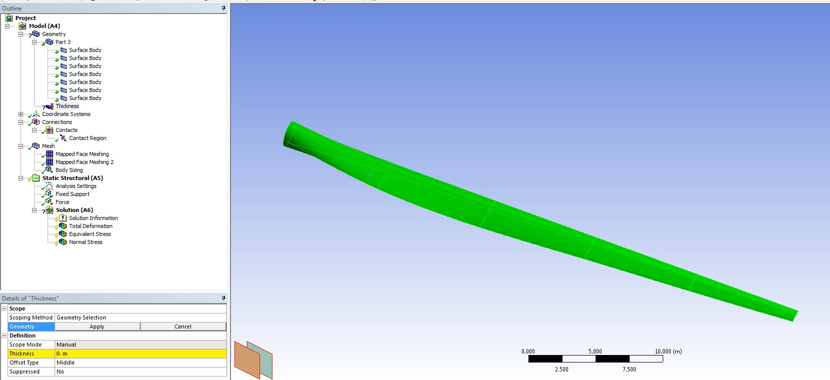
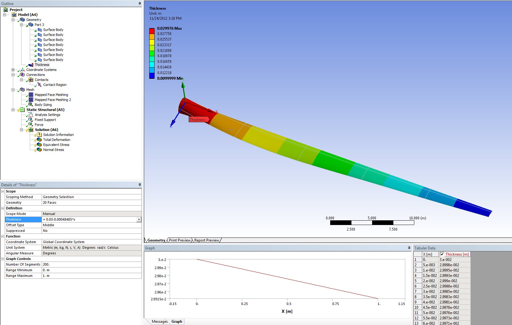
Select function from the drop down list in Thickness. Enter the thickness as a function of length: 0.03-0.00048485*x. The thickness graphics will be displayed:
The thickness of the spar is 0.02 meters. Locate the appropriate surface bodies that represent the spar and change the thickness to 0.02 meters.

Connections
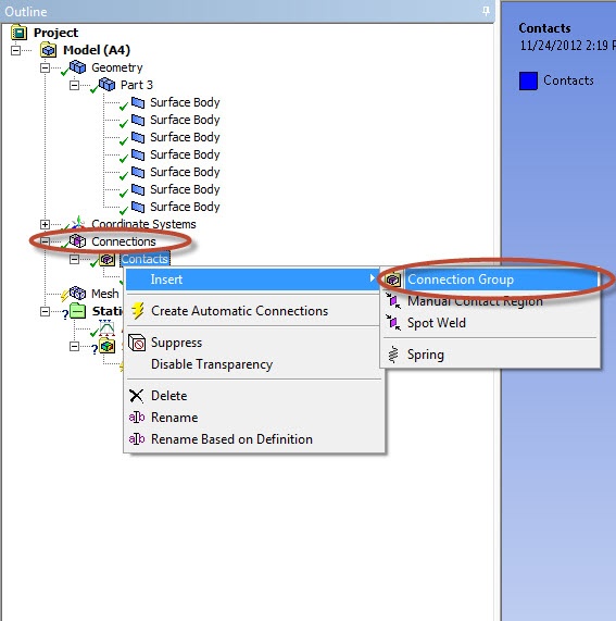
The contact between the wind blade and the spar needs to be modeled. Right click on Connections and insert a Connection Group.
In the connection group named Contacts 2, change the Face/Face detection to No and Face/Edge detection to Yes.

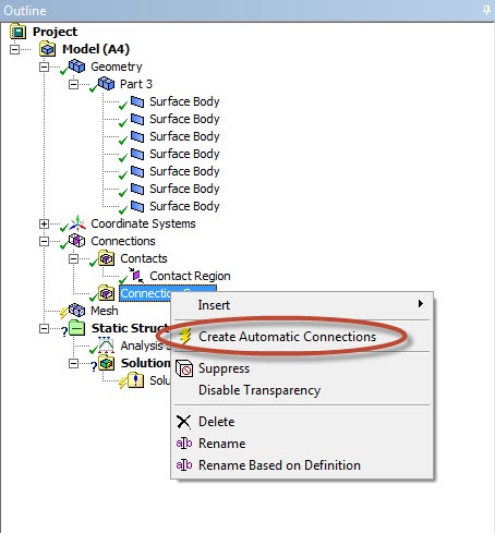
Right click on Contacts 2 and click on Create Automatic Connections.
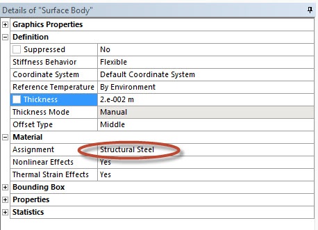
Material Properties
For each surface body, check that Structural Steel is assigned as the material.
Fixed Support
We will fix the ring at the end of the blade. To accomplish this, click on Static Structural (B5) to bring up the Environment menu bar. In the Environment menu bar, select Supports > Fixed Support. Next, make sure the edge selection filter  is selected. Hold Ctrl, and click on the 2 edges that make up the ring at the end shoulder of the blade (see image below).
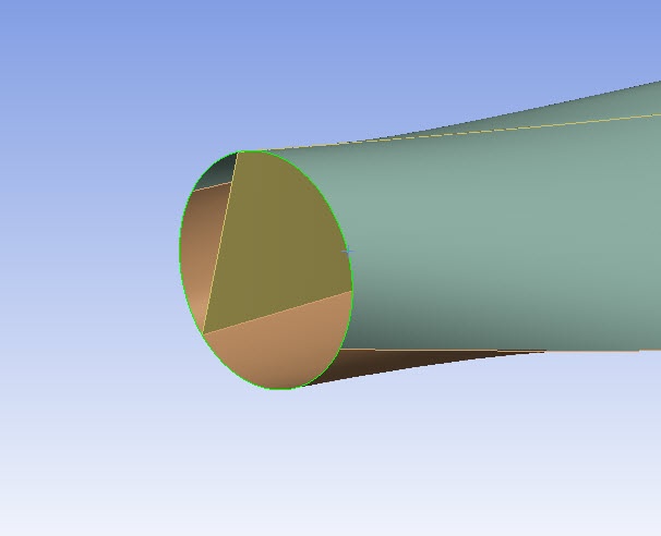
When both edges have been selected, press Geometry > Apply.
Force Load
We want to apply a 1000 N downward force on the blade. To initialize a force load, in the Environment menu bar select Loads > Force. Make sure the surface selection filter  is selected and choose the two upper surface of the end of blade, as shown in the image below.
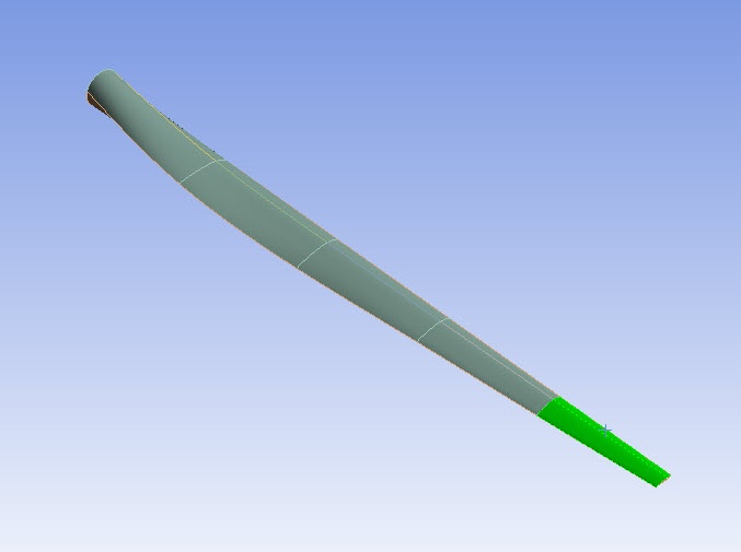
When the surface have been selected, press Geometry > Apply in the Details window. Next, select Define By > Components. Define the Y Component as -1000 N.

We are now ready to set up the solution and solve.
Go to Step 5: Numerical Solution
Go to all ANSYS Learning Modules
...
Author: Ben Mullen, Cornell University
...