...
...
3. Mesh
Launch Mechanical
In order to start Mechanical (Double Click) Model,  Image Removed.
Mapped Face Meshing
| Include Page |
|---|
| 2D Steady Conduction - Panel |
|---|
| 2D Steady Conduction - Panel |
|---|
|
 Image Added
Create Mesh
| HTML |
|---|
<iframe width="640" height="360" src="https://www.youtube.com/embed/eAczNX7uF98" frameborder="0" allowfullscreen></iframe> |
Effect on Numerical Solution Procedure
| HTML |
|---|
<iframe width="640" height="360" src="https://www.youtube.com/embed/WtWi9l9A_NM" frameborder="0" allowfullscreen></iframe> |
Go to Step 4: Model Setup
Go to all ANSYS Learning ModulesFor this simulation we will use a mapped face mesh. A mapped face mesh is that a mesh that can be mapped to a rectangular domain. The domain for this simulation is already rectangular, thus mapped faced meshing will yield a rectangular grid mesh. In order to implement the mapped face meshing, first (Click) Mesh,  Image Removed. Next, (Click) Mesh Control > Mapped Face Meshing, as shown below.
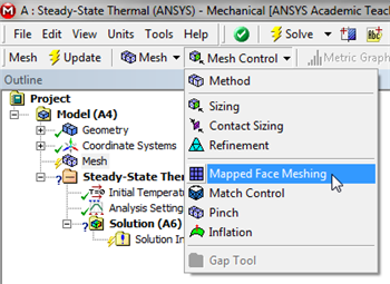 Image Removed
| newwindow |
|---|
Click Here for Higher Resolution | Click Here for Higher Resolution | https://confluence.cornell.edu/download/attachments/146918513/MFM_Full.png |
Then, click on the rectangle and it should highlight green. If it does not highlight green, click on the face selection filter button,  Image Removed,then click on the rectangle. Once the rectangle has been selected (Click) Apply in the "Details of Mapped Face Meshing" table as shown below.
 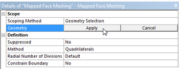 Image Removed
| newwindow |
|---|
Click Here for Higher Resolution | Click Here for Higher Resolution | https://confluence.cornell.edu/download/attachments/146918513/DMFM_Full.png |
Now, (Click) Update,  Image Removed, in order to generate the mesh. You should obtain the following mesh.
 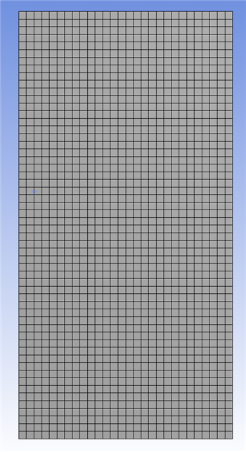 Image Removed
| newwindow |
|---|
Click Here for Higher Resolution | Click Here for Higher Resolution | https://confluence.cornell.edu/download/attachments/146918513/GenMesh_Full.png |
This completes the meshing process for this simulation.
 Sign-up for free online course on ANSYS simulations!