 Sign-up for free online course on ANSYS simulations!
...
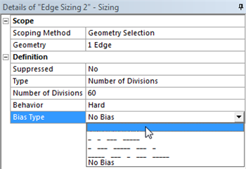
We would like to have more elements in the region very close to the flate plate and less elements in the far field. In order to do this, we must bias the edge sizing. First, click on Edge Sizing 2, then click on Bias Type and set it to the first option as shown below.
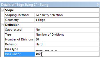
Next, set the Bias Factor to 100 as shown below. The Bias Factor is defined in this case to be the ratio of the longest division and the shortest division. That is, the last division will be one hundred times longer than the length of the first division.
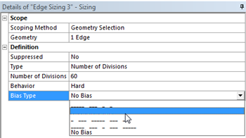
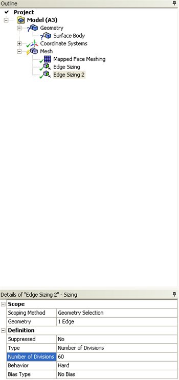
Now, the biasing needs to be specified for the right side of the geometry. In order to incorporate the biasing on the right side a new Edge Sizing needs to be implemented. First, (Click) Mesh Control > Sizing. Then, select and apply the left side of the geometry. Then, change Type to Number of Divisions and set Number of Divisions to 60. Next, set Behavior to Hard and set Bias Type to the second option, as shown below.
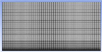
Then, set the Bias Factor to 100. Lastly, click Update to generate the new mesh. You should obtain the following mesh.
| newwindow | ||||
|---|---|---|---|---|
| ||||
https://confluence.cornell.edu/download/attachments/90737915/BiasedMesh_Full.png |
Meshing Method
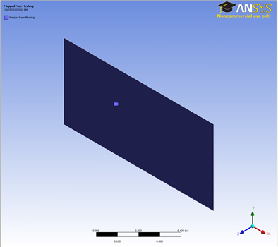
We would also like to create a structured mesh where the opposite edges correspond with each other. Let's insert a Mapped Face mesh. Under Outline, right click on Mesh, move cursor to Insert, and select Mapped Face Meshing. Alternatively, you can click on Mesh Control on the third menu and select Mapped Face Meshing. Finally select the flat plate surface body in the Graphics window and click Apply next to Geometry.
This is what you should end up with;
Edge Sizing
Now let us move on to specify the element sizing along the pipe radial direction.
Outline > Mesh > Insert > Sizing
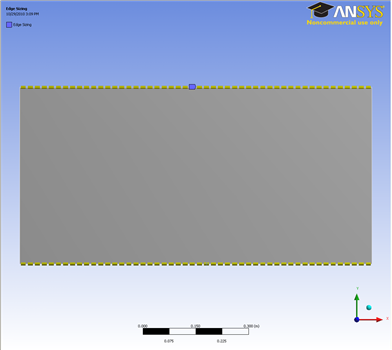
In the Graphics window, select both the top and bottom edges of the geometry (click on the Edge tab on the Fluid flow Fluent - Mesh window and then press Ctrl + mouse click to multiple select). Under Details of "Edge Sizing", click Apply next to Geometry. Change the edge sizing definition Type to Number of Divisions. Enter 50 for Number of Divisions. Next to Behaviour, change Soft to Hard
You should have something that looks like this;
Now continue with the sizing in the y-axis direction.
Outline > Mesh > Insert > Sizing
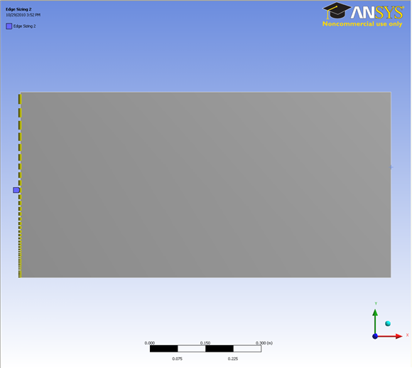
In the Graphics window, select the left side edge of the geometry (press Ctrl + mouse click to multiple select). Under Details of "Edge Sizing", click Apply next to Geometry. Change the edge sizing definition Type to Number of Divisions. Enter 60 for Number of Divisions. Next to Behaviour, change Soft to Hard (This is to overwrite the sizing function employed by ANSYS Mesher). Then under Bias Type enter 100.
You should get this;
Now follow the same steps for the right side edge sizing as delineated for the left side above.
...
Create Named Selections
Here, the edges of the geometry will be given names so one can assign boundary conditions in Fluent in later steps. The left side of the pipe will be called "Inlet" and the right side will be called "Outlet". The top side of the rectangle will be called "PipeWall" and the bottom side of the rectangle will be called "CenterLine" as shown in the image below.
| newwindow | ||||
|---|---|---|---|---|
| ||||
https://confluence.cornell.edu/download/attachments/85624045/Naming_Full.png |
In order to create a named selections first (Click) Edge Selection Filter,
 . Then click on the left side of the rectangle and it should highlight green. Next, right click the left side of the rectangle and choose Create Named Selection as shown below.
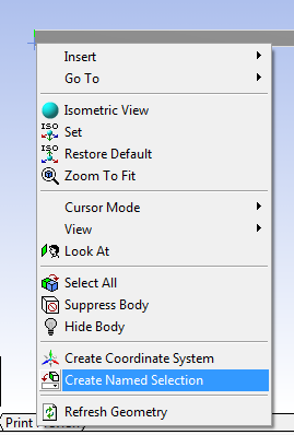
We have specified all the meshing conditions. Click Update on the third menu to see the mesh.
It should look like this;
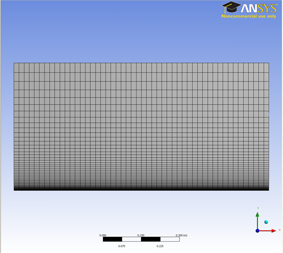
Click on Mesh and look under Details of "Mesh", next to Statistics, you should see that we have 6120 Elements for our mesh.
Create Named Selection
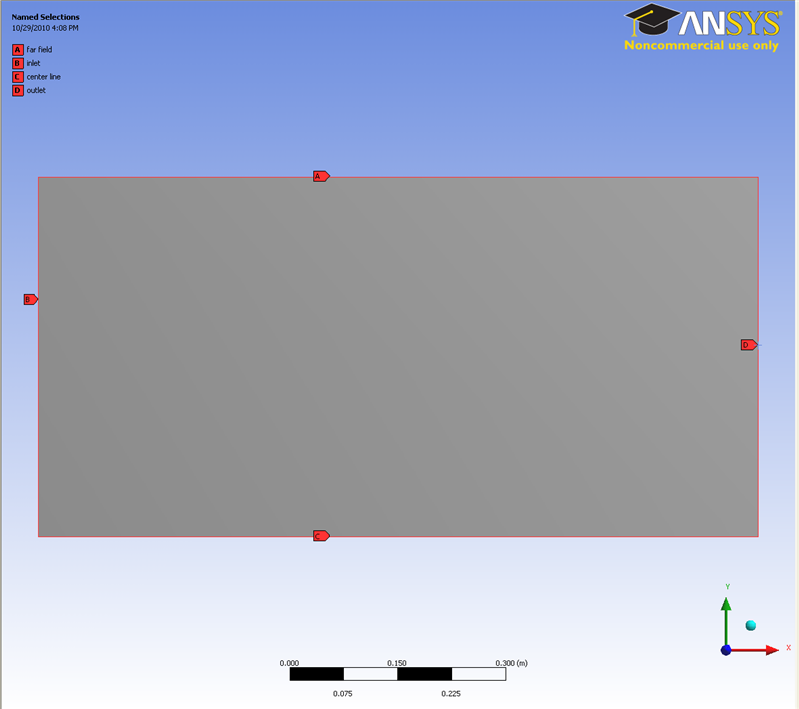
Next, we will name the edges accordingly so that we can specify the appropriate boundary conditions in the later step. We know the bottom edge of the geometry is the center line of the flat plate, the left edge is the inlet of the flat plate, the right edge is the outlet, top side edge is the far field. Remember to click on the Edge tab on the Fluid flow Fluent - Mesh window and then press Ctrl + mouse click to multiple select the 3 line sections that make up the center line before naming it.
Select the left edge and right click and select Create Named Selection. Enter Inlet and click OK. Under Outline, you will see the name Inlet under Named Selections. Note that the flat plat surface is designated as the center line.
Finish naming rest of the edges.
Then,type "Inlet" into the text prompt and press ok as shown below.
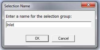
Now, create named selections for the remaining three sides and name them according to the diagram.
Save, Exit & Update
First save the project. Next, close the Mesher window. Then, go to the Workbench Project Page and click the Update Project button,  Finally, click Update.
Go to Step 4: Setup (Physics)