 Sign-up for free online course on ANSYS simulations!
...
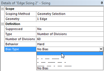
We would like to have more elements in the region very close to the flate plate and less elements in the far field. In order to do this, we must bias the edge sizing. First, click on Edge Sizing 2, then click on Bias Type and set it to the first option as shown below.
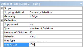
Next, set the Bias Factor to 100 as shown below. The Bias Factor is defined in this case to be the ratio of the longest division and the shortest division. That is, the last division will be one hundred times longer than the length of the first division.
Now, the biasing needs to be specified for the right side of the geometry. In order to incorporate the biasing on the right side a new Edge Sizing needs to be implemented. First, (Click) Mesh Control > Sizing. Then, select and apply the left side of the geometry. Then, change Type to Number of Divisions and set Number of Divisions to 60. Next, set Behavior to Hard and set Bias Type to the second option, as shown below.
Meshing Method
We would also like to create a structured mesh where the opposite edges correspond with each other. Let's insert a Mapped Face mesh. Under Outline, right click on Mesh, move cursor to Insert, and select Mapped Face Meshing. Alternatively, you can click on Mesh Control on the third menu and select Mapped Face Meshing. Finally select the flat plate surface body in the Graphics window and click Apply next to Geometry.
...