...
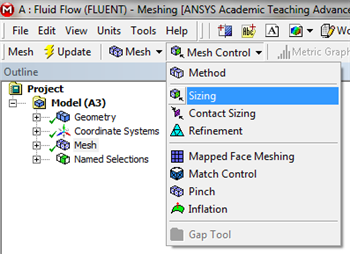
The desired mesh has specific number of divisions in the x direction and a specific number of divisions in the y direction. In order to obtain the specified number of divisions Edge Sizing must be used. The divisions in the x direction will be specified first. Now, an Edge Sizing needs to be inserted. First, (Click) Mesh Control > Sizing as shown below.
| newwindow |
|---|
| Click Here For Higher Resolution |
|---|
| Click Here For Higher Resolution |
|---|
|
https://confluence.cornell.edu/download/attachments/85624045/MenuSizing_Full.png |
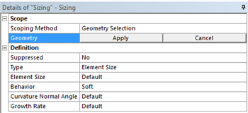
Now, the geometry and the number of divisions need to be specified. First
(Click) Edge Selection Filter,
 Image Modified
. Then hold down the "Control" button and then click the bottom and top edge of the rectangle. Both sides should highlight green. Next, hit
Apply under the
Details of Sizing table as shown below.
| newwindow |
|---|
| Click Here For Higher Resolution |
|---|
| Click Here For Higher Resolution |
|---|
|
https://confluence.cornell.edu/download/attachments/85624045/DetSizing_Full.png |
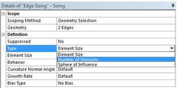
Now, change
Type to
Number of Divisions as shown in the image below.
| newwindow |
|---|
| Click Here For Higher Resolution |
|---|
| Click Here For Higher Resolution |
|---|
|
https://confluence.cornell.edu/download/attachments/85624045/NumbDiv_Full.png |
Then, set
Number of Divisions to
100 50 as shown below.
 Image Removed
| newwindow |
|---|
Click Here For Higher Resolution | Click Here For Higher Resolution | https://confluence.cornell.edu/download/attachments/85624045/SetTo100_Full.png 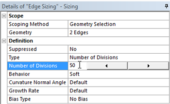 Image Added Next, set the Behavior to Hard as shown in the image below. This step will disable the ANSYS Mesher from overwriting any of our edge sizing specifications.
 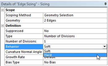 Image Added
 At this point, the edge sizing in the the
radial y direction will be specified. Follow the same procedure as for the edge sizing in the axial direction, except select the left and right side instead of the top and bottom and set the number of division to
560. Remember to set the Behavior to Hard. Then,
click Update to generate the mesh
by using either method from the "Default Mesh" section abovewith the new specifications. You should obtain the following mesh.
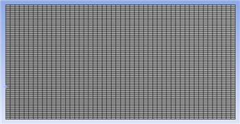 Image Added
| newwindow |
|---|
| Click Here For Higher Resolution |
|---|
| Click Here For Higher Resolution |
|---|
|
https://confluence.cornell.edu/download/attachments/85624045/DefEdgeMesh_Full.png |
| newwindow |
|---|
| Click Here For Higher Resolution |
|---|
| Click Here For Higher Resolution |
|---|
|
https://confluence.cornell.edu/download/attachments/85624045/DefEdgeMesh_Full.png |
As it turns out, in the mesh above there are 540 elements, when there should be only 500. Mesh statistics can be found by clicking on
Mesh in the Tree and then by expanding
Statistics under the
Details of Mesh table. In order to get the desired 500 element mesh the
Behavior needs to be changed from
Soft to
Hard for both
Edge Sizing's. In order to carry this out first
Expand Mesh in the tree outline then click
Edge Sizing and then change
Behavior to
Hard under the
Details of Edge Sizing table, as shown below.
| newwindow |
|---|
| Click Here For Higher Resolution |
|---|
| Click Here For Higher Resolution |
|---|
|
https://confluence.cornell.edu/download/attachments/85624045/BehaviorHard_Full.png |
Then set the
Behavior to
Hard for
Edge Sizing 2. Next, generate the mesh using either method from the "Default Mesh" section above. You should then obtain the following 500 element mesh.
| newwindow |
|---|
| Click Here For Higher Resolution |
|---|
| Click Here For Higher Resolution |
|---|
|
https://confluence.cornell.edu/download/attachments/85624045/FinMesh_Full.png |
| newwindow |
|---|
| Radial Sizing |
|---|
| Radial Sizing |
|---|
|
https://confluence.cornell.edu/download/attachments/111221571/Radial+Sizing.gif |
...
 Sign-up for free online course on ANSYS simulations!