 Sign-up for free online course on ANSYS simulations!
| Panel |
|---|
Problem Specification |
Step 2: Geometry
Since our problem involves fluid flow, we will select the FLUENT component on the left panel.
...
At this point, a new window, ANSYS Design Modeler will be opened. You will be asked to select desired length unit. Use the default meter unit and click OK.
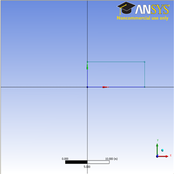
Creating a Sketch
Start by creating a sketch on the XYPlane. Under Tree Outline, select XYPlane, then click on Sketching right before Details View. This will bring up the Sketching Toolboxes.
...
You should have something like this:
Dimensions
Now we will specify the appropriate dimensions and constraints. Below is the summary of geometry flat plate boundary layer:
...