 Sign-up for free online course on ANSYS simulations!
...
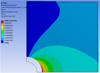
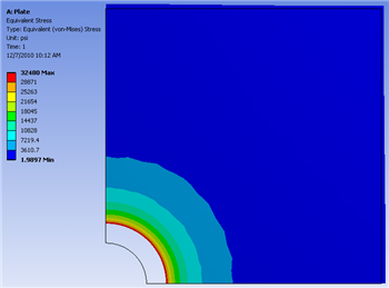
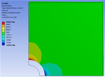
At this point the Candidate A results will be inputted back into the Design Modeler. That, is the radius from Candidate A will be set as the radius of the hole in Design Modeler. In order to do so, (Right Click) Candidate A > Insert as Design Points. Next, click Return to Project and double click on Parameter Set. In the "Table of Design Points" (Right Click) Current > Duplicate design point then (Right Click) DP1 > Copy Inputs to Current. In the previous commands you saved the previous current design point by moving it to DP2 and you have inserted Candidate A into the Current design point. Now, click Update All Design Points. Now, the radius of Candidate A has been inserted as the radius in the Design Modeler. Next, click Return to Project and double click Results. Now, the graphical results for the Candidate A radius of 1.4725 inches can be viewed. The graphs below display the directional deformation, the equivalent Von Mises stress and the normal stress respectively.
Directional Deformation (X Direction)
Equivalent Von Mises Stress
Normal Stress
Go to Step 7: Verification & Validation
...