 Sign-up for free online course on ANSYS simulations!
...
| Include Page | ||||
|---|---|---|---|---|
|
| Note |
|---|
This tutorial was created with an older version of ANSYS (14.5), where the mesh generator and the refinement process was not as strong as it is now. This will result in a different solution than the one shown. (In ANSYS 16.1, the optimization results in a radius of ~1.25in-1.27in and in ANSYS 2019 R2 the optimization results in a radius of ~1.11-1.13in) |
Optimization
Set-Up of Optimization
...
The optimization should yield similar results to the following table. Surprise! Some candidate points do not satisfy the maximum Von Mises stress constraint (now marked with a red cross). This is why it is important to always verify the candidate points.
Note: In version 2019 R2, we found that all three of the candidate points failed at this step, so don't be concerned if that is what you find.
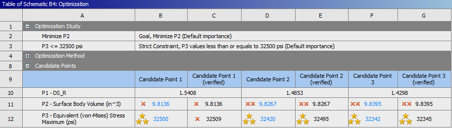
By selecting candidate points under the results section of the Outline of Schematic B4: Optimization window, you can also see how the results of each candidate points differ from the results of a specified reference candidate point. Additionally, you can even add new candidate points.
...
Tip: Remember how we specified the radius to range from 1 to 2.5 inches to create the Response Surface? Well we now know that the optimized radius should be around 1.45 inches so no need to have that big of a of range anymore. For a second round of optimization (not done in this tutorial), it would be a good idea to go back in Design of Experiments and change to the lower and upper bound bounds to be, say 1.4 and 1.5 inches respectively. A smaller range will give you a more accurate response surface which will help you optimize the radius further.
Obtaining
...
Deformation and Stress Results for Selected Design Point
We will select candidate point 2 as the design point. It is a good idea to review the deformation and stress plots at the chosen design point. To do this, let's set the
...
At this point the Candidate Point 2 results will be inputted back into the Design Modeler. That is, the radius from Candidate Point 2 will be set as as the radius of the hole in Design Modeler. In order to do so, Select (Right Click) Candidate Point 2 > Insert as Design Point.
...
Next, click Return to Project and double click on Parameter Set. Selecting insert as design point, for candidate point 2, Insert as Design Point created the design point DP1. In Now in the "Table of Design Points" (Right Click) Current > Duplicate design point.
...