 Sign-up for free online course on ANSYS simulations!
...
We would also like to create a structured mesh where the opposite edges correspond with each other. Let's insert a Mapped Face mesh. Under Outline, right click on Mesh, move cursor to Insert, and select Mapped Face Meshing. Alternatively, you can click on Mesh Control on the third menu and select Mapped Face Meshing. Finally select the flat plate surface body in the Graphics window and click Apply next to Geometry.
This is what you should end up with; 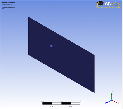
Edge Sizing
Now let us move on to specify the element sizing along the pipe radial direction.
Outline > Mesh > Insert > Sizing
In the Graphics window, select both the left and right edge of the geometry (click on the Edge tab on the Fluid flow Fluent - Mesh window and then press Ctrl + mouse click to multiple select). Under Details of "Edge Sizing", click Apply next to Geometry. Change the edge sizing definition Type to Number of Divisions. Enter 30 for Number of Divisions.
...