 Sign-up for free online course on ANSYS simulations!
Step 4: Specify geometry
Since the geometry excluding the cutout region is symmetric with respect to the vertical centerline, we will model half of the crank and then mirror the other half to complete the crank body. Then we will create the cutout from a set of keypoints.
Create a Rectangular Area
Main Menu > Preprocessor > Modeling > Create > Areas > Rectangle > By 2 Corners
...
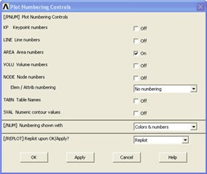
Check the box next to AREA Area numbers to turn on area numbering. Click OK.
Create Circular Areas
Main Menu > Preprocessor > Modeling > Create > Areas > Circle > Solid Circle
...
To correct any mistakes, you must click Main Menu > Preprocessor > Modeling > Delete > Areas Only and then pick each area you want to remove. The mouse pointer will show an up arrow for picking areas and a down arrow for un-picking areas. Right-click to switch between pick and unpick mode. When you have made all your selections, click OK. Click Utility Menu > Plot > Replot to refresh the view.
Add Areas
Main Menu > Preprocessor > Modeling > Operate > Booleans > Add > Areas
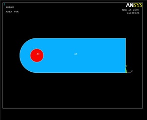
Pick the rectangular and large circular areas. Click OK. (This is where the area numbering may come in handy) The result should look like the image below.
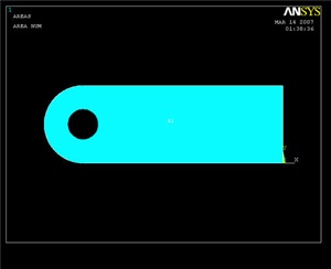
Subtract Hole Area
Now we create the hole by subtracting the round area from the rest of the crank.
...
First pick the body of the crank and click OK. Then pick the hole, and click OK again. The result is shown below.
Reflecting the Area
To create the other half of the crank, we will reflect the current area about the Y-Z plane.
...
| newwindow | ||||
|---|---|---|---|---|
| ||||
https://confluence.cornell.edu/download/attachments/82384582/crank1.jpg?version=1 |
Creating Keypoints for the Cut-out Region
Since the material to be removed in the middle of the crank is an irregular shape, we will define some keypoints in order to create and subtract this area.
...
(-0.7972, 0.1642)
(0.7972, 0.3248)
(0.7972, 0.9744)
(-0.7972, 1.1368)
The result:
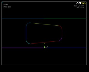
Creating Lines and Fillets from Keypoints
Main Menu > Preprocessor > Modeling > Create > Lines > Lines > Straight Line
...
Pick two lines that meet at a corner where you want to put a fillet, then click OK. Enter a Fillet radius of 0.177, and click Apply. Repeat for the other three corners of the quadrilateral. Compare results with image below.
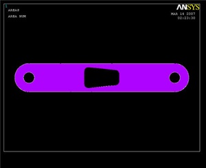
Finishing the Crank Face
All that's left now is to create a new area from the filleted quadrilateral region, and then subtract it from the rest of the crank face.
...
| Info | ||
|---|---|---|
| ||
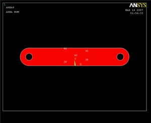
The result:
Creating the Volume
We will now make the face 3-D by extruding it by a given offset distance, similar to modeling in CAD.
...
| newwindow | ||||
|---|---|---|---|---|
| ||||
https://confluence.cornell.edu/download/attachments/82384582/crank3d.jpg?version=1 |
Creating the Pedal Shaft
Main Menu > Preprocessor > Modeling > Create > Volumes > Cylinder > Solid Cylinder
...
| newwindow | ||||
|---|---|---|---|---|
| ||||
https://confluence.cornell.edu/download/attachments/82384582/crank+with+shaft.jpg?version=1 |
Save Your Work
Toolbar > SAVE_DB