 Sign-up for free online course on ANSYS simulations!
...
In the Crank cell, right click on Geometry, and click New Geometry...
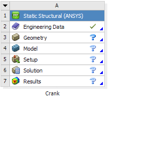
At this point, a new window, ANSYS Design Modeler will be opened. You will be asked to select desired length unit. Select Inch unit and click OK.
...
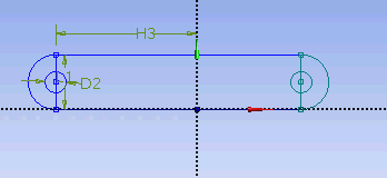
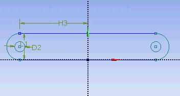
Input value for D2, H3, L1 respectively under Details View tab.
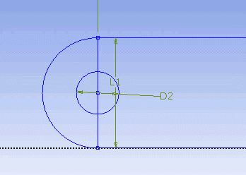
D2 = 0.5 in
H3 = 3.3465 in
L1 = 1.299 in
Note: Your dimension naming might not be the same as the one shown here. It is fine. Just make sure your value correspond to correct dimensions.
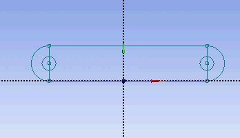
Next, we need to make sure that the sketch is symmetry on both side. Under Sketching Toolboxes, select Constraints tab. Select Midpoint and constraint the geometry in the Graphics window as shown below.
Next, we will make sure that the both circular hole is of same dimension. Under Constraints tab, select Equal Radius. Execute constraint in the Graphics window as shown below.

We will next trim off the unwanted edge. Under Modify tab, select Trim. Execute the trimming in Graphics window as shown below.
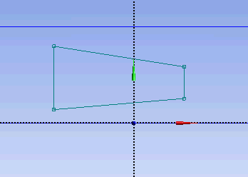
At this point, we have the outline of the crank done. We need to add the cut out in the middle of the crank. First start with a sketching of the cut-out. Under Draw tab, click on Line and execute drawing in Graphic window as shown below.
We would want the four corners of the cut out we created to be of following coordinate.
(-0.7972, 0.1642)
(0.7972, 0.3248)
(0.7972, 0.9744)
(-0.7972, 1.1368)
Unfortunately, there is no easy way in specifying the coordinates of a point. So we will have to dimension them accordingly using the dimensioning tools. Click on Dimensions tab and use General tool and execute the dimensioning as shown.
Under Details View, enter the value for the dimensions.
H5 = 0.7972 in
H6 = 0.7972 in
L4 = 0.1642 in
...