| Include Page |
|---|
| SIMULATION: ANSYS - Crank - Panel |
|---|
| SIMULATION: ANSYS - Crank - Panel |
|---|
|
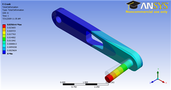
Step 6: Results
Let first look at Total Deformation. Under Solution (F6), click on Total Deformation. The Total Deformation plot is then shown in the Graphics window. The maximum deflection is 0.026644 in. We should check that our results make sense. It appears that the boundary conditions have been satisfied as the tip of the shaft moves downward and the hole at the other end of the crank is held in place.
| newwindow |
|---|
| Higher Resolution Image |
|---|
| Higher Resolution Image |
|---|
|
https://confluence.cornell.edu/download/attachments/111238805/Total%20Deformation.png |
Note: To show the original undeformed crank, go to third menu and click onand finally click.
You can also animate the deformation by clicking play button right underGraphicswindow.
Von Mises Stress
Now let's look at the stress on the crank. Left clicking on Equivalent Stress under Solution (F6). In the Graphics window show the crank stress contour. The maximum stress is 27897 psi.
| newwindow |
|---|
| Higher Resolution Image |
|---|
| Higher Resolution Image |
|---|
|
https://confluence.cornell.edu/download/attachments/111238805/Total%20Deformation.png |
 Sign-up for free online course on ANSYS simulations!