 Sign-up for free online course on ANSYS simulations!
Author: Rajesh Bhaskaran & Yong Sheng Khoo, Cornell University
Problem Specification
1. Pre-Analysis & Start-Up
2. Geometry
3. Mesh
4. Setup (Physics)
5. Solution
6. Results
7. Verification & Validation
Step 6: Results
Total Deformation
Let first look at Total Deformation. Under Solution (F6), click on Total Deformation. The Total Deformation plot is then shown in the Graphics window. The maximum deflection is 0.026644 in. We should check that our results make sense. It appears that the boundary conditions have been satisfied as the tip of the shaft moves downward and the hole at the other end of the crank is held in place.

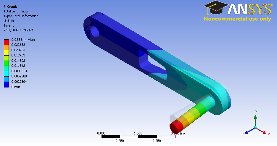
Note: To show the original undeformed crank, go to third menu click  and click on
Notice the deformation is exaggerated, revealing that deformation is primarily caused by torsion.
You can also animate the deformation by clicking play button right under Graphics window.

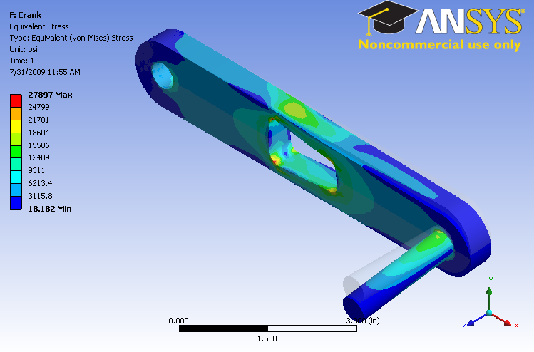
Von Mises Stress
Now let's look at the stress on the crank. Left clicking on Equivalent Stress under Solution (F6). In the Graphics window show the crank stress contour. The maximum stress is 27897 psi.

Here's the view without the handle.

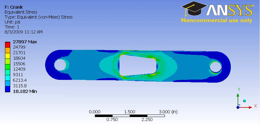
Note: To hide the crank handle, select the appropriate body in the Graphics window and right click and select Hide Body. Do the same to unhide a body.
Go to Step 7: Verification & Validation