 Sign-up for free online course on ANSYS simulations!
...
Next to FD1, Depth (>0), enter value 0.5 in. Click Generate.
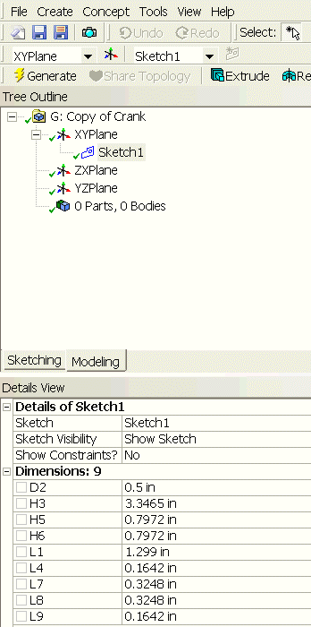
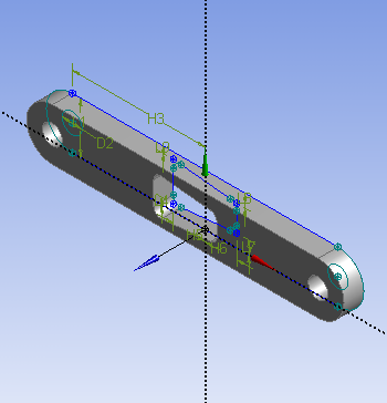
Note that after you click Generate, you see a new part created under the Tree Outline. This is what you should have in the Graphic window at this point.
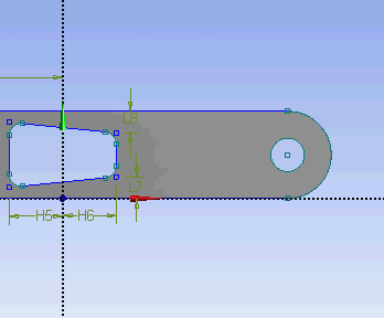
Now let's keep moving by adding a handle to this crank. Under Tree Outline, click on XY Plane and click on New Sketch  . This will create a new sketch under XY Plane. You will see Sketch2 created under XYPlane. Click on the Sketching tab to start sketching the handle. The base sketch for the handle is just a cycle. Under Draw tab, click on Circle.
Execute the drawing in the Graphics window as shown below.
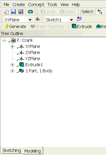
At this point, we have the crank handle sketch done. We can continue adding Extrude feature to the sketch. Click Extrude, make sure that Sketch2 is selected next to Base Object. Next to Operation change Add Material to Add Frozen. This is because we want to create the crank as two separate bodies. If we use the default Add Material, both the crank and crank handle will be created as a single body. Next to FD1, Depth (>0) enter value of 2.645. We can now Generate this feature. Under Tree Outline, you will see that we have now 2 Parts and 2 Bodies. Select on both parts and perform Form New Part operation.
...