...
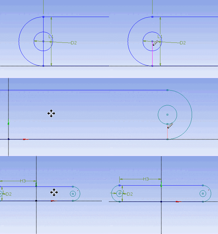
We will next trim off the unwanted edge. Under Modify Tab, select Trim. Execute the trimming in Graphic window as shown below.
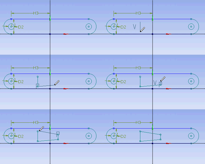
At this point, we have the outline of the crank done. We need to add the the cut out in the middle of the crank. First start with a sketching of the cut-out. Under Draw tab, click on Line execute drawing in Graphic window as shown below.
We would want the four points of the cut out we created to be of following coordinate.
(-0.7972, 0.1642)
(0.7972, 0.3248)
(0.7972, 0.9744)
(-0.7972, 1.1368)
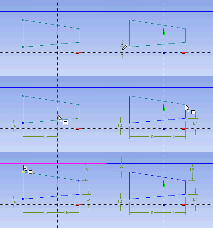
Unfortunately, there is no easy way in specifying the coordinates of a point. So we will have to dimension them accordingly using the dimensioning tools. Click on Dimensions tab and use General tool and execute the dimensioning as shown.
Under Details View, enter the value for the dimensions.
H5 = 0.7972 in
H6 = 0.7972 in
L4 = 0.1642 in
L7 = 0.3248 in
L8 = 0.3248 in
L9 = 0.1642 in
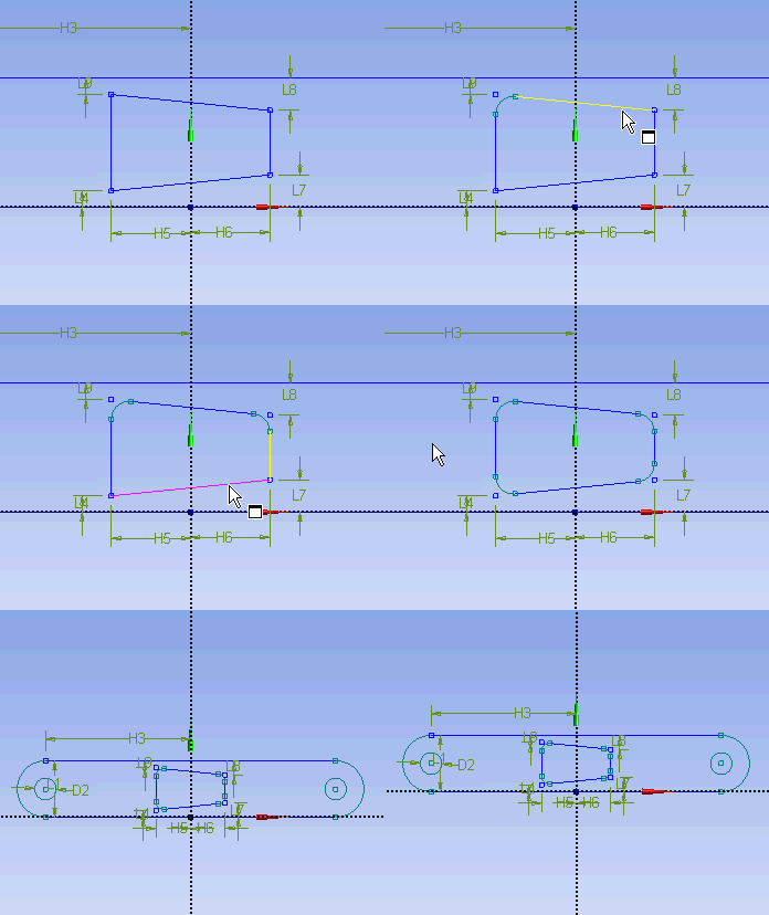
Next we will add fillet to the corner of the cut out. Click on Modify tab and select Fillet. Enter a Radius value of 0.177 in. Execute the command in Graphics window as shown.
Now we have the sketch of the crank done. Next we will perform extrude feature on this sketch.
See and rate the complete Learning Module
...
 Sign-up for free online course on ANSYS simulations!


