 Sign-up for free online course on ANSYS simulations!
...
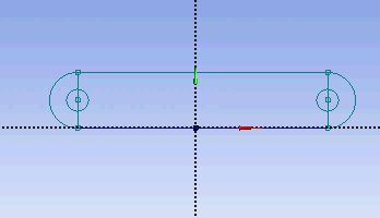
Next, we will dimension the current drawing. Under Sketching Toolboxes, select Dimensions tab. You will see a list of dimensioning options. We will use the default General option. Execute the geometry dimensioning as shown below.
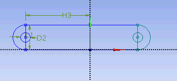
Input value for D2, H3, L1 respectively under Details View tab.
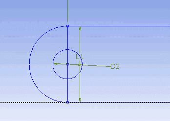
D2 = 0.5 in
H3 = 3.3465 in
L1 = 1.299 in
Note: Your dimension naming might not be the same as the one shown here. It is fine. Just make sure your value correspond to correct geometry.
Next, we need to make sure that the sketch is symmetry on both side. Under Sketching Toolboxes, select Constraints tab. Select Midpoint and constraint the geometry in the Graphic window as shown below.
Next, we will make sure that the both circular hole is of same dimension. Under Constraints tab, select Equal Radius. Execute constraint in the Graphic window as shown below.

We will next trim off the unwanted edge. Under Modify Tab, select Trim. Execute the trimming in Graphic window as shown below.
At this point, we have the outline of the crank done. We need to add the
Select Rectangle. Create a rough Rectangle from starting from the origin in the positive XY direction (Make sure that you see a letter P at the origin before you start dragging the rectangle. The letter P at the origin means the geometry is constrained at the origin.
You should have something like this:
Note: You do not have to worry about geometry for now, we can dimension them properly in the later step.
Modify the Sketch
Since we have a heated section in the middle of the pipe, we need to split the geometry appropriately. Click Modify tab and select Split. Roughly select four points on the top and bottom of the rectangle where there will be heated section.
Dimensions and Constraints
Now we will specify the appropriate dimensions and constraints. Below is the summary of geometry of the pipe:
Radius: 0.0294 m
Length: 6.096 m
Heated Section: 1.83 m - 4.27 m
Select Dimensions tab, use the default dimensioning tools. Dimension the geometry as shown:
Under Details View on the lower left corner, input the value for dimension appropriately.
V1: 0.0294 m
H2: 1.83 m
H3: 4.27 m
H4: 6.096 m
Now we can constraint the lower rectangle with the top of the rectangle which has been properly dimensioned. Click Constraints tab, select Equal Length. Click the appropriate top and bottom edge and set them to be of equal length.
At this point, you should see something like this for your sketch:
Now that we have the sketch done,
See and rate the complete Learning Module
...