 Sign-up for free online course on ANSYS simulations!
...
Step 3: Specify Boundary Types in GAMBIT
Following figure shows different boundary type.
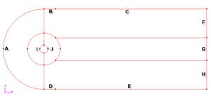
(Click picture for larger image)
(Label the farfield accordingly)
We will label edge A as farfield1, the top boundary as farfield2, bottom boundary as farfield3, right boundary as farfield4 and the cylinder surface as cylinder.
Label the boundary according to the table shown below
Edges | Group Name |
Left | farfield 1 |
Top | farfield 2 |
Bottom | farfield 3 |
Right | farfield 4 |
Cylinder | cylinder |
These We'll label the boundary AFE as farfield1, ABDE as farfield2 and the airfoil surface as airfoil. Recall that these will be the names that show up under boundary zones when the mesh is read into FLUENT.
Group Edges
We'll create groups of edges and then create boundary entities from these groups.
First, we will group AF and EF togetherGroup the appropriate edges accordingly.
Operation Toolpad > Geometry Command Button > Group Command Button > Create Group
...