 Sign-up for free online course on ANSYS simulations!
| Panel |
|---|
Problem Specification |
Step 3: Specify
...
Boundaries in GAMBIT
Following figure shows different boundary type.
We'll label the boundary AFE as farfield1, ABDE as farfield2 and the airfoil surface as airfoil. Recall that these will be the names that show up under boundary zones when the mesh is read into FLUENT.
Group Edges
We'll create groups of edges and then create boundary entities from these groups.
First, we will group AF and EF together.
Operation Toolpad > Geometry Command Button > Group Command Button > Create Group
Select Edges and enter farfield1 for Label, which is the name of the group. Select the edges AF and EF.
Note that GAMBIT adds the edge to the list as it is selected in the GUI.
Click Apply.
In the transcript window, you will see the message "Created group: farfield1 group".
![]()
Similarly, create the other two farfield groups. You should have created a total of three groups:
Group Name | Edges in Group |
|---|---|
farfield1 | AF,EF |
farfield2 | AB,DE |
farfield3 | BC,CD |
airfoil | HI,IG,HJ,JG (name might vary) |
Define Boundary Types
Now that we have grouped each of the edges into the desired groups, we can assign appropriate boundary types to these groups.
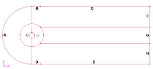
Label the boundaries according to the figure shown below.
| newwindow | ||||
|---|---|---|---|---|
| ||||
https://confluence.cornell.edu/download/attachments/103729621/step3_img001.jpg?version=1 |
We will label edge A as farfield1, edges B and C as farfield2, edges D and E as farfield3, edges E,G and H as farfield4 and the edges I and J as cylinder.
Edges | Name |
A | farfield 1 |
B,C | farfield 2 |
D,E | farfield 3 |
F,G,H | farfield 4 |
I,J | cylinder |
Operation Toolpad > Zones Command Button ![]() > Specify Boundary Types
> Specify Boundary Types ![]()
Under Entity, select Groups.
Select any edge belonging to the airfoil surface and that will select the airfoil groupSpecify boundary according to the table above. Next to Name:, enter airfoilthe name accordingly. Leave the Type as WALL.
Click Apply.
In the Transcript Window, you will see a message saying "Created Boundary entity: airfoil".
Similarly, create boundary entities corresponding to farfield1, farfield2 and farfield3 groups. Set the Type to Pressure Farfield in each caseWe will specify boundary type using FLUENT.
Save Your Work
Main Menu > File > Save
...
Main Menu > File > Export > Mesh...
Save the file as airfoil cylinder.msh.
Make sure that the Export 2d Mesh option is selected.
Check to make sure that the file is created.
Go to Step 4: Set Up Problem in FLUENT
See and rate the complete Learning Module
...