 Sign-up for free online course on ANSYS simulations!
| Panel |
|---|
Problem Specification |
...
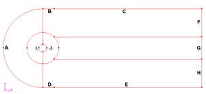
Label the boundaries according to the figure shown below.
 (Click picture for larger image)
| newwindow | ||||
|---|---|---|---|---|
| ||||
https://confluence.cornell.edu/download/attachments/103729621/step3_img001.jpg?version=1 |
We will label edge A as farfield1, edges B and C as farfield2, edges D and E as farfield3, edges E,G and H as farfield4 and the edges I and J as cylinder.
Edges | Name |
A | farfield 1 |
B,C | farfield 2 |
D,E | farfield 3 |
E F,G,H | farfield 4 |
I,J | cylinder |
Operation Toolpad > Zones Command Button ![]() > Specify Boundary Types
> Specify Boundary Types ![]()
!btype_cb.jpg|width=32,height=32!Specify boundary according to the table above. Next to Name, enter the name accordingly. Leave the Type as WALL. We will specify boundary type using FLUENT.
...
Main Menu > File > Export > Mesh...
Save the file as cylinder{{.msh}}.
Make sure that the Export 2d Mesh option is selected.
Check to make sure that the file is created.
Go to Step 4: Set Up Problem in FLUENT
See and rate the complete Learning Module
...