 Sign-up for free online course on ANSYS simulations!
...
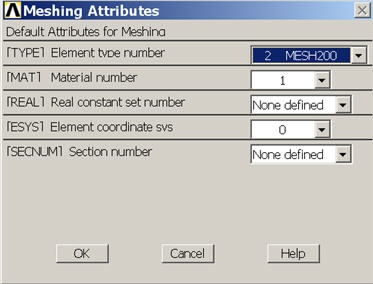
We'll first mesh the two front surfaces using MESH200. Click Set next to Global under Element Attributes. Set the TYPE to MESH200 and click OK.
According to the ANSYS manual, "Smart element sizing (SmartSizing) is a meshing feature that creates initial element sizes for free meshing operations. SmartSizing gives the mesher a better chance of creating reasonably shaped elements during automatic mesh generation ... The SmartSizing algorithm first computes estimated element edge lengths for all lines in the areas or volumes being meshed. The edge lengths on these lines are then refined for curvature and proximity of features in the geometry." To turn on SmartSizing, check the box next to Smart Size. Drag the slider to a size of 4 to get a finer mesh than the default.
In order to have a little more control over what mesh ANSYS creates for us, we will set the starting element size for SmartSizing rather than use the default. Smartsizing will take this starting element size and modify/vary it over the geometry to account for curvature and corners. Under Size Controls, click the Set button next to Global. Enter an element edge length of 0.12 and click OK. The specified smart size of 4 and edge length of 0.12 are the result of an iterative process. You should experiment with different settings for these parameters to study the effect of the mesh on your solution, as discussed in Step 9. The goal is to obtain a solution that doesn't change as you refine the mesh.
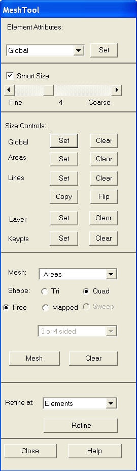
Select Areas to be meshed with a Quad shape using the Free mesher. Click Mesh. Pick the front face of the crank and the pedal shaft.
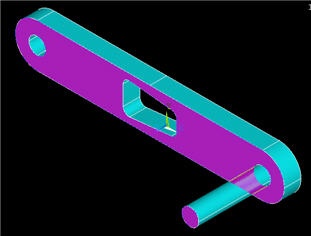
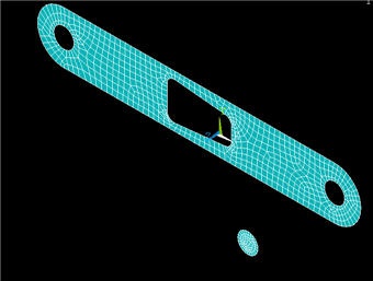
Click OK. You will now see:
You'll get the following warning:
...
Bring up the MeshTool again. Click Set next to Global under Element Attributes. Set the TYPE to SOLID45 and click OK. We want four layers of mesh elements to span the thickness of the crank, so the desired element edge length in the sweep direction is (0.5 /4) = 0.125 in. Under Size Controls, click the Set button next to Global. Enter an element edge length of 0.125 and click OK. We will now sweep, i.e. extrude, the surface meshes created above across the corresponding volumes. Select Volumes to be meshed with a Hex shape along with the Sweep option as shown below. Make sure Auto Src/Trg is selected; this will automatically pick a source (Src) surface mesh and sweep/extrude it to a target (Trg) surface.
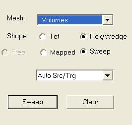
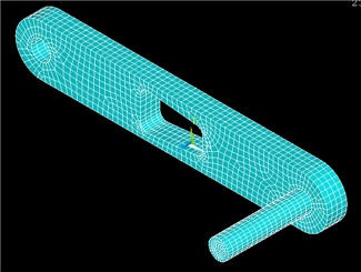
Click Sweep and Pick All to sweep-mesh both volumes. ANSYS will extend our previous surface meshes across the corresponding volumes.
...