 Sign-up for free online course on ANSYS simulations!
Step 4: Specify geometry
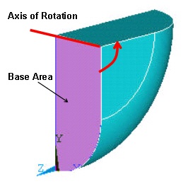
Because of the inherent symmetry of the model, we'll perform the analysis on a quarter of the volumes only. Recall that a=0 (i.e. angle between the planes in which radii R1 and R2 lie is zero). As a result, the upper and lower volume have the same orientation, when viewed from the top.
...
We will define the origin of the coordinate system to be at the point of contact.
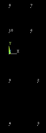
Create Keypoints
Main Menu > Preprocessor > Modeling > Create > Keypoints > In Active CS
...
Keypoint 10: X =0, Y =R1-inter, Z =0, Click OK.
Create Lines
Main Menu > Preprocessor > Modeling > Create > Lines > Lines >In Active Coord
...
This brings up the Arc by End KPs and Radius menu. Enter {{R1| for RAD Radius of the arc. The other parameters (keypoints at start, end and center of curvature) are automatically selected and we don't need to change them. Click Apply.
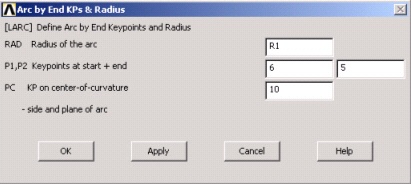
Similarly, create the arc between keypoints 2 and 1, using keypoint 9 as the center-of-curvature and R2 as the RAD Radius of the arc.
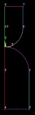
At this point we have all the lines and arcs needed to create the areas.
Create Areas
Main Menu > Preprocessor >Modeling > Create > Areas > Arbitrary > By Lines
...
Note that you can also generate the areas by creating two squares and two circular sectors, and then adding them using boolean operations. This method generates the same end result. |
Create Volumes
To create the volumes, we will rotate each of the areas about a line/axis.
...
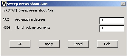
This brings up the Sweep Areas about Axismenu. This menu allows you to specify the angle by which the area will be rotated about the axis. Clearly, we want to rotate the area 90 degrees to generate the volume, but there are two options: +90 or -90. The sign is determined by the keypoint selection made in the previous step. Since we selected keypoint 8 first and then keypoint 7, the axis goes from 8 to 7. As a result, we want to rotate the area +90 degrees (use the right hand rule to visualize this) so that the area is rotated in the negative z direction. Enter 90 for ARC Arc length in degrees. Since we don't want segments or divisions in the volume, enter 0 for NSEG No. of volume segments. Click Apply.
Repeat the same procedure to generate the lower volume. Start by selecting the lower area (2). Click OK. Then select keypoint 3 first and then keypoint 4, click OK. In the following menu, enter 90 for ARC Arc length in degrees and 0 for NSEG No. of volume segments. Click OK.
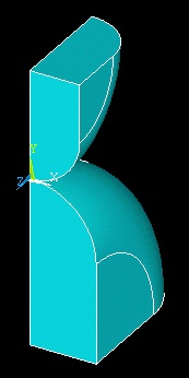
If you did this correctly, you will see that both areas are rotated 90 degrees in the negative z direction. Note that the key step here is to specify a rotation angle consistent with your selection of initial and final keypoints, following the right hand rule.
Save Your Work
Toolbar > SAVE_DB
Go to Step 5: Mesh geometry
...