 Sign-up for free online course on ANSYS simulations!
Problem Specification*
[1. Start-up and preliminary set-up|SIMULATION:Step 1 Start-up and preliminary set-up]
[2. Specify element type and constants|SIMULATION:Step 2 Specify element type and constants]
[3. Specify material properties|SIMULATION:Step 3 Specify material properties]
[4. Specify geometry|SIMULATION:Step 4 Specify geometry]
[5. Mesh geometry|SIMULATION:Step 5 Mesh geometry]
6. Specify boundary conditions
7. Solve
8. Postprocess the results
9. Validate the results
Step 6: Specify boundary conditions
...
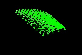
This brings up the Apply U,Rot on Areas menu. Select UY for the DOFs to be constrained and enter 0 for the Displacement value. Click OK.
...
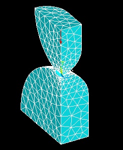
This brings up the Apply F/M on KPs pick menu. Select keypoint 8 on the upper body and click OK. This brings up the Apply F/M on Keypoints menu. Select FY for the Direction of force/mom. Enter - p/4 for Force/Moment value and click OK. A single red arrow denotes the force and the direction in which it is acting. Note that we have divided the total force P=4500N by four to account for the fact that only a quarter of the volumes are being modeled.
...
This brings up the Define Coupled DOFs menu. Enter 1 for Set reference number which is an arbitrary number. Select UY for Degree-of-freedom labelas we want to couple the movement of the nodes in the y direction. This step ensures that all nodes on the upper surface will move equally as a result of the applied load. Click OK.
...
Save Your Work
Toolbar > SAVE_DB
Go to Step 7: Solve!