 Sign-up for free online course on ANSYS simulations!
Step 6: Specify boundary conditions
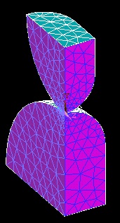
As in previous tutorials, we'll apply the loads to the geometry rather than the mesh.
One important change to note is that instead of applying force P to the lower disk, we'll constrain the lower surface of the lower disk in the vertical (Y) direction in order to sufficiently constrain the model and avoid rigid body motion.
Apply Symmetry Boundary Conditions
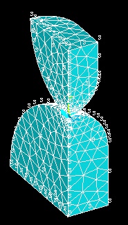
We'll apply symmetry boundary conditions along the planes of symmetry.
Main Menu > Preprocessor > Loads > Define Loads > Apply > Structural > Displacement > Symmetry B.C. > On Areas
Select the four areas that define the planes of symmetry by clicking on them.
Click OK. The symbol s appears along these areas indicating that symmetry B.C.s have been applied.
Apply Displacement Constraints
Main Menu > Preprocessor > Loads > Define Loads > Apply > Structural > Displacement > On Areas
This brings up the Apply U,Rot on Areas pick menu. Select the bottom area of the lower disk (x-z plane). Click OK.
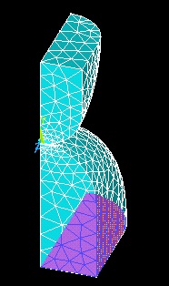
This brings up the Apply U,Rot on Areas menu. Select UY for the DOFs to be constrained and enter 0 for the Displacement value. Click OK.
Apply Force
Main Menu > Preprocessor > Loads > Define Loads > Apply > Structural > Force/Moment > On Keypoints
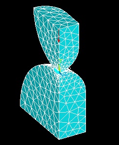
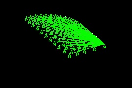
This brings up the Apply F/M on KPs pick menu. Select keypoint 8 on the upper body and click OK. This brings up the Apply F/M on Keypoints menu. Select FY for the Direction of force/mom. Enter p/4 for Force/Moment value and click OK. A single red arrow denotes the force and the direction in which it is acting. Note that we have divided the total force P=4500N by four to account for the fact that only a quarter of the volumes are being modeled.
Apply Coupled BCs
We will apply a coupled boundary condition to the upper area of the upper disk to ensure that all nodes attached to this area move equally as a result of the applied load.
Utility Menu > Select > Entities
Select Areas from the pull-down menu at the top and By Num/Pick below that. Select From Full below that. Click Apply.
Hold down the left mouse button until area 6 is selected. Area 6 is the upper area (x-z plane) of the upper disk. Click OK.
Next we'll select the nodes attached to this area. In the Select Entities menu, select Nodes from the pull-down menu at the top and Attached to below that. Select Areas, All below that. Click OK.
Verify that only nodes attached to area 6 are currently selected: Utility Menu > Plot > Nodes
We'll now apply a coupled boundary condition to the selected nodes.
Main Menu > Preprocessor > Coupling/Ceqn > Couple DOFs
This brings up the Define Coupled DOFs pick menu. In the Input window, ANSYS tells you to "Pick or enter nodes to be coupled". Since we have already selected the nodes, click Pick All.
This brings up the Define Coupled DOFs menu. Enter 1 for Set reference number which is an arbitrary number. Select UY for Degree-of-freedom labelas we want to couple the movement of the nodes in the y direction. This step ensures that all nodes on the upper surface will move equally as a result of the applied load. Click OK.
Before we move to the next step, we need to undo the selection of nodes and areas we have made. Select everything: Utility Menu > Select > Everything.
Save Your Work
Toolbar > SAVE_DB
Go to Step 7: Solve