 Sign-up for free online course on ANSYS simulations!
Author: Rajesh Bhaskaran & Yong Sheng Khoo, Cornell University
Problem Specification
1. Pre-Analysis & Start-up
2. Geometry
3. Mesh
4. Setup (Physics)
5. Solution
6. Results
7. Verification & Validation
Problem 1
Problem 2
Step 1: Pre-Analysis & Start-up
Since the nozzle has a circular cross-section, it's reasonable to assume that the flow is axisymmetric. So the geometry to be created is two-dimensional.
Start GAMBIT
Create a new folder called nozzle and select this as the working directory. Add -id nozzle to the startup options.
Create Axis Edge
We'll create the bottom edge corresponding to the nozzle axis by creating vertices A and B shown in the problem specification and joining them by a straight line.
Operation Toolpad > Geometry Command Button ![]() >Vertex Command Button
>Vertex Command Button ![]() >Create Vertex
>Create Vertex ![]()
Create the following two vertices:
Vertex 1: (-0.5,0,0)
Vertex 2: (0.5,0,0)
Operation Toolpad > Geometry Command Button ![]() > Edge Command Button
> Edge Command Button ![]() > Create Edge
> Create Edge ![]()
Select vertex 1 by holding down the Shift button and clicking on it. Next, select vertex 2. Click Apply in the Create Straight Edge window.
Create Wall Edge
We'll next create the bottom edge corresponding to the nozzle wall. This edge is curved. Since
A = Πr2
where r( x ) is the radius of the cross-section at x and
A = 0.1 + x2
for the given nozzle geometry, we get
r( x ) = [(0.1 + x2)/Π]0.5; -0.5 < x < 0.5
This is the equation of the curved wall. Life would have been easier if GAMBIT allowed for this equation to be entered directly to create the curved edge. Instead, one has to create a file containing the coordinates of a series of points along the curved line and read in the file. The more number of points used along the curved edge, the smoother the resultant edge.
The file vert.dat contains the point definitions for the nozzle wall. Take a look at this file. The first line is
21 1
which says that there are 21 points along the edge and we are defining only 1 edge. This is followed by x,r and z coordinates for each point along the edge. The r-value for each x was generated from the above equation for r( x ) . The z-coordinate is 0 for all points since we have a 2D geometry.
Right-click on vert.dat and select Save As... to download the file to your working directory.
Main Menu > File > Import > ICEM Input ...
Next to File Name:, enter the path to the vert.dat file that you downloaded or browse to it by clicking on the Browse button.
Then, check the Vertices and Edges boxes under Geometry to Create as we want to create the vertices as well as the curved edge.

Click Accept.
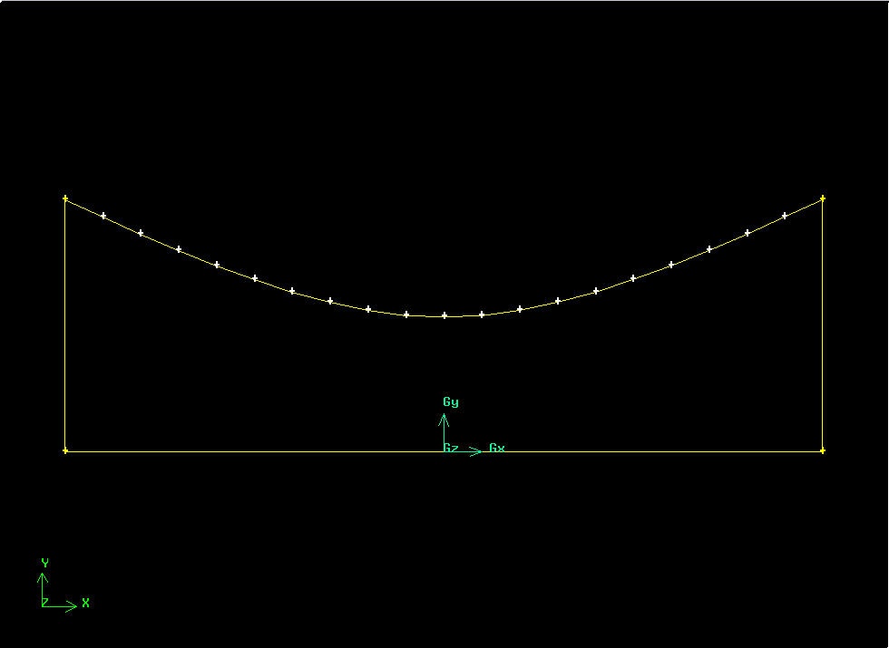
This should create the curved edge. Here it is in relation to the vertices we created above:


Create Inlet and Outlet Edges
Create the vertical edge for the inlet:
Operation Toolpad > Geometry Command Button ![]() > Edge Command Button > Create Edge
> Edge Command Button > Create Edge
Shift-click on vertex 1 and then the vertex above it to create the inlet edge.
Similarly, create the vertical edge for the outlet.

Create Face
Form a face out of the area enclosed by the four edges:
Operation Toolpad > Geometry Command Button ![]() >Face Command Button
>Face Command Button ![]() >Form Face
>Form Face ![]()
Recall that we have to shift-click on each of the edges enclosing the face and then click Apply to create the face.
Save Your Work
Main Menu > File > Save
This will create the nozzle.dbs file in your working directory. Check that it has been created so that you will able to resume from here if necessary.