 Sign-up for free online course on ANSYS simulations!
Author: Ben Mullen, Cornell University
Problem Specification
1. Pre-Analysis & Start-Up
2. Geometry
3. Mesh
4. Physics Setup
5. Numerical Solution
6. Numerical Results
7. Verification & Validation
Exercises
Comments
Geometry
For users of ANSYS 15.0, please check this link for procedures for turning on the Auto Constraint feature before creating sketches in DesignModeler.
Download Geometry Files
Click here to download the geometry. Save the file somewhere convenient, such as your desktop.
Load the Geometry into ANSYS
In ANSYS, go to File > Import. This will allow us to import the geometry from outside ANSYS into our workspace. First, make sure the file extension box is set to Geometry File . Next, browse to geometry file, select it, and press OK . The geometry file should now appear in the Project Schematic window.

Open the Geometry
Next, open the geometry file by double clicking it in the Project Schematic window.

This will open the Design Modeler . When the design modeler loads, we will first need to specify a standard unit. Select Inch and press OK .

As you can probably tell, ANSYS does not generate the model automatically, so we need to generate the geometry. Click  to generate the geometry.

Create a Flow Geometry
Caps
The next step is for us to create a flow geometry. The air is going to flow through the inside of the box; however, we need to create a geometry for this empty space in order for ANSYS to be able to calculate the solution. We will accomplish this by creating Caps , then using those caps to create Fill . In the menu bar, select Tools > Fill. In the Details window, name the fill Caps , and make sure the extraction type is set to By Cavity .

We need to create caps for the two inlet holes, the two outlet holes, and all 16 connection holes. In order to create a cap, a cavity is identified by faces and ANSYS will fill the cavity with material. Most holes are identified by two faces. Notice in the figure below that in the large cavity, one section has been selection (green) and the other is not selected. In order to create a fill for the cavity, both surfaces need to be selected.

To select these surfaces, use the Face Selection Filter  Hold down CTRL to select multiple surfaces at once. When all the surfaces have been selected, press Faces > Apply in the Details window. 40 surfaces should have been selected.
Fill
Next, we need to create the fill geometry. Once again, go to Tools > Fill. Name the fill, FlowGeometry. Also, we need to change the Extraction Type . Select Extraction Type > By Caps . The other parameters should be left as their defaults. Press to create the fill geometry.

Form New Part
In the Outline window, select all of the parts in the tree, right click, and select Form New Part

Connect Geometry to Project
Finally, we are ready to connect the geometry to the project. Close the design modeler, and return to the Project Schematic. Connect the geometry to the project by clicking and dragging the Geometry to Mesh
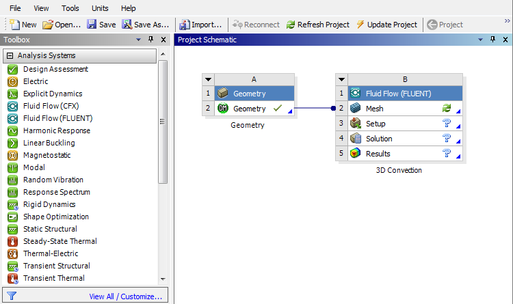
Once the geometry has been connected, save the project.
Go to Step 3: Mesh