Chemical Dose Controller
Abstract
At the Cuatro Comunidades plant, the operator sets the plant's alum dose using a chemical dose controller (CDC). The appropriate alum dose varies based on two factors, the incoming turbidity and the plant flow rate. The CDC is designed to maintain a constant dose regardless of changes in the plant flow rate. The CDC at the plant was monitored and improvements were made to the original model. The actual chemical doses were compared with the theoretical doses for both models.

Introduction and Objectives
The original CDC used in the Cuatro Communidades plant was the first generation of the technology used by AguaClara, (Figure 1). The CDC was made up of three components--- a flow control module (FCM), lever arm and a sutro weir. The alum flow rate into the plant was set by the available head between the FCM inlet valve and outlet hose. The available head was changed by moving the outlet hose along the lever arm. Once the hose was positioned on the lever arm, the flow rate should have been constant regardless of the available head in the alum stock tank. The sutro weir was used to create a linear relationship between plant flow rate and the height of water in entrance tank. The lever arm united the first two components of the CDC. The outlet hose of the FCM was connected to one end of the lever arm while a float balanced the opposite end of the fulcrum. The float height varied with the water level in the entrance tank which was determined by the sutro weir. When the float rose, the opposite end of the lever arm with the FCM outlet hose fell increasing available head in the FCM and therefore increasing the alum dose. The coordination of plant flow rate and alum dose decreased the number of variables involved in selecting an appropriate alum dose.
The alum dose was set by positioning the outlet hose of the CDC at a certain distance from the fulcrum of the lever arm. As the plant flow rate rose the end of the lever arm attached to the dosing hose angled further downward. By moving the dosing hose further away from the fulcrum, the hose outlet was also moved downward with respect to the inlet of the FCM, increasing the head available to drive the alum flow rate. This relationship between distance along the lever arm and increasing alum dose should be linear. Over the course of the summer, the alum flow rate was measured and the CDC system was monitored to detect any failure modes. After observing the original CDC, an improved aluminum model was constructed. The theoretical and actual flow rates for both CDCs are compared below.
Methods
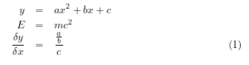
The alum doses delivered by both the original PVC lever arm and the aluminum model were measured. The alum dose was determined by measuring the flow rate delivered by the CDC. The dose was then calculated using the equation:
where:
- C dose was the alum dose
- Q FCM was the alum flow rate
- C stock was the chemical stock concentration
- Q plant was the plant flow rate
This actual dose was then compared to the theoretical dose. Two different methods were used to measure the flow rate. For the PVC lever arm the flow was measured by filling a graduated cylinder for thirty seconds. The alum flow rate of the original CDC was measured every time the operator changed the dose. The alum flow rate tests were performed over a series of weeks.
For the aluminum CDC, a more accurate measurement method was implemented to obtain the flow rate data. A clear PVC pipe was inserted between the chemical stock tank and the flow control module (Figure 2).

To measure flow rate, the first valve from the stock tank to the PVC pipe was opened and the PVC pipe was filled. The line bypassing the PVC pipe was then shut off and the time for the cylinder to empty to obtain the actual flow rate was measured.
Results and Discussion
Original CDC

As can be seen in figure 4, the actual dose delivered by the CDC was highly variable close to the fulcrum, and the CDC was consistently under dosing further along the lever arm. Thirty centimeters away from the fulcrum the CDC was supposed to deliver a maximum dose of 60 mg/L. However, the CDC was only dosing an average of 35 mg/L. The range of doses provided by this CDC was appropriate for most incoming turbidities (<200 NTU) to the plant. However, the dose was not adequate for the high turbidity raw water coming to the plant after a rainstorm. Additionally the variability in the dose made it impossible to associate a particular distance along the lever arm with a specific alum dose.

Some of this variability is inevitably due to the fact that the measurements were taken on different days and the FCM outlet hose may have been clogged when the measurements were taken. However, several defects in the lever arm design were also noted, and a new model was made. The original design consisted of a PVC lever arm with notches cut into it for each chemical dose. The dosing hose and a pressure break tee were moved up and down the lever arm by a loop of fishing line and a knot that could be attached to each slit, (figure 5). The notches on the slit meant the operator could only choose incremental doses. The alum dose at each notch should have been constant. However, the fishing line connection could be adjusted within each notch so the dose was not consistent with location. Furthermore the lever arm was not located at a sufficient height in the entrance tank. At high flow rates the end of the lever arm was submerged, (figure 6).

At high plant flow rates, when the water level in the entrance tank rose, the pressure break tee and hosing floated above the water level. This may have decreased the distance between the hose outlet and the level arm. If this was true, then the CDC was delivering lower doses at higher plant flow rates.
Additionally, the sutro weir often clogged with leaves if it was not constantly monitored and cleaned. Leaves and grit blocked the open surface area of the sutro weir and increased the height of water in the entrance tank when there was no change in the plant flow rate. Because the alum dose was based on the height of water in the entrance tank and not directly on the plant flow rate, the alum dose increased as well. This issue can be fixed by better monitoring and cleaning on the part of the operator. To eliminate the problem for the operator a new configuration of larger holes that is not easily clogged could be designed or a prescreening system could be put in place before the sutro weir.
Aluminum CDC

A new lever arm was constructed and monitored. The lever arm was made of a rust resistant bar of aluminum (Figure 7). The FCM outlet hose slid along the lever arm and fixed in place by a screw. This sliding system gave the operator more flexibility when choosing an alum dose. The hose hung from a short aluminum bar. The difference between theoretical and actual chemical flow rates was measured for this lever arm as well. The actual alum doses of this chemical doser can be seen in Figure 8.

The data in figure 8 was taken after the FCM hosing had been cleaned and was taken over the span of several hours rather than several weeks as was the case in figure 3. Each actual dose point represents the average of three trials. The results show that the dose is increasing linearly with plant flow rate as expected. However, the CDC was still incapable of reaching the higher end of the design flow rates. Again, the maximum dose did not reach 60 mg/L. This means that there was too much head loss in the hosing system of the FCM. The length of the hose controls the head loss in the system. Shortening this hose would increase the maximum flow rate. Another way to increase the maximum dose delivered by the CDC would be to lengthen the lever arm which would give the ability to position the outlet hose further below the inlet of the FCM.
From figure 8, it is impossible to say whether the variability in the chemical dose at each location on the lever arm improved. The system used to measure the flow rate was more precise. The data was only taken at one plant flow rate and the system had just been cleaned. The data taken with the original PVC lever arm was taken at multiple plant flow rates and the system was not necessarily clean when each data point was taken.

A final adjustment was made after this test to reduce variability in the dose--- the hose was directly attached to the lever arm and the short aluminum bar was removed (figure 9). The short aluminum bar could be attached to on position along the lever arm at an angle changing the distance between the hose and the FCM inlet. The change was made to fix the distance between the FCM inlet and outlet hose at each position. This will help maintain a constant dose at each lever arm position. Additionally, the change increased the distance between the hose and the water level in the entrance tank so the hose will not be submerged at high plant flow rates.
Conclusions
The CDC did show the linear relationship between outlet hose position along the lever arm and alum dose that was expected. However the system was consistently under dosing the maximum alum doses. This can be fixed by shortening the dosing hose or lengthening the lever arm. The connection between the dosing hose and the lever arm should be rigid in order to ensure that the distance of the hose outlet from the lever arm is constant as the hose is moved along the lever arm. Further investigation should be made to see if the variability of dose delivered at a specific position along the lever arm can be improved.