| Name | Size | Creator | Creation Date | Labels | Comment | ||
|---|---|---|---|---|---|---|---|
| JPEG File A.in diagram.jpg | 7 kB | user-1194e | Oct 28, 2009 17:10 |
|
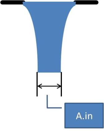
This is a diagram meant to help explain the calculation of the flow area used as A.in for the flow expansion coefficient and in the calculation of the head loss through the large and small scale mixing orifices. | ||
| Version 1 (current) | 7 kB | user-1194e | Oct 28, 2009 17:10 | This is a diagram meant to help explain the calculation of the flow area used as A.in for the flow expansion coefficient and in the calculation of the head loss through the large and small scale mixing orifices. | |||
| JPEG File EntTank_RMTube_FlocTank.jpg | 81 kB | user-1194e | Oct 28, 2009 19:36 |
|
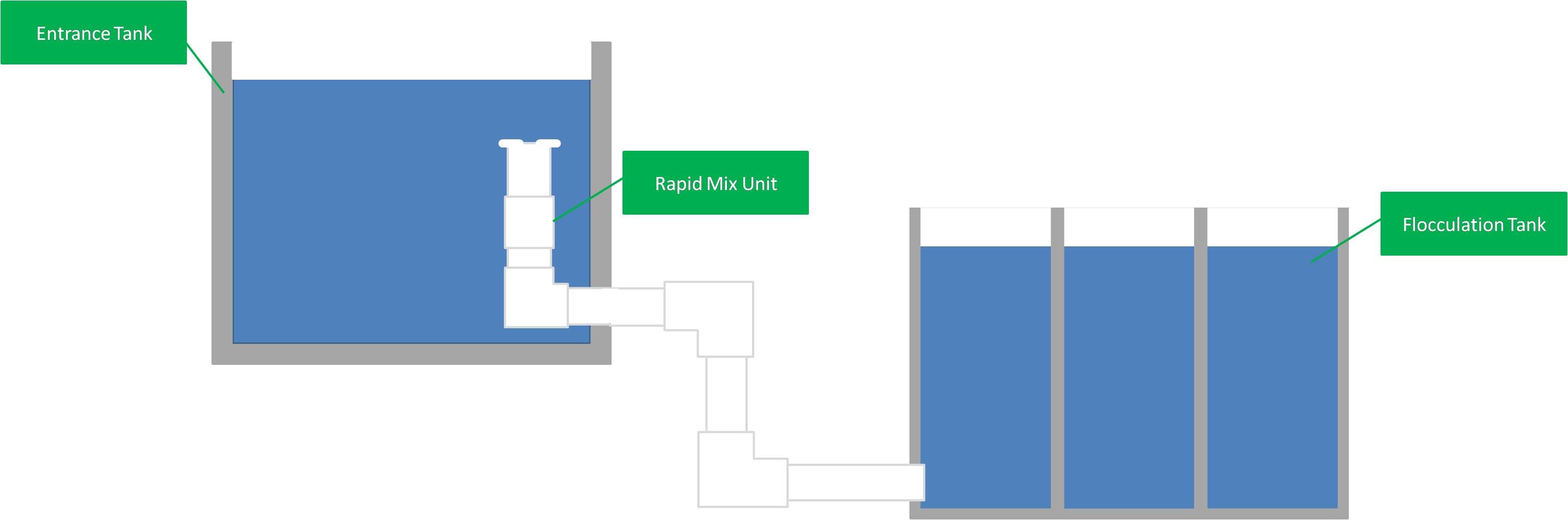
This diagram shows the progression of water flow from the entrance tank through the rapid mix tube and finally into the flocculator. | ||
| Version 1 (current) | 81 kB | user-1194e | Oct 28, 2009 19:36 | This diagram shows the progression of water flow from the entrance tank through the rapid mix tube and finally into the flocculator. | |||
| JPEG File Proposed_RMTube_Schematic.jpg | 51 kB | user-1194e | Oct 28, 2009 19:36 |
|
This is a diagram of the rapid mix tube as I originally proposed it to be built. | ||
| Version 1 (current) | 51 kB | user-1194e | Oct 28, 2009 19:36 | This is a diagram of the rapid mix tube as I originally proposed it to be built. | |||
| Microsoft Powerpoint Presentation expansion losses.pptx | 149 kB | user-1194e | Oct 29, 2009 09:50 |
|
This is a powerpoint that references many of the equations used to design the rapid mix tube system. The most important components are the expansion loss equations presented in the powerpoint lecture. | ||
| Version 1 (current) | 149 kB | user-1194e | Oct 29, 2009 09:50 | This is a powerpoint that references many of the equations used to design the rapid mix tube system. The most important components are the expansion loss equations presented in the powerpoint lecture. | |||
| JPEG File initial RM design.jpg | 78 kB | user-1194e | Oct 29, 2009 10:27 |
|
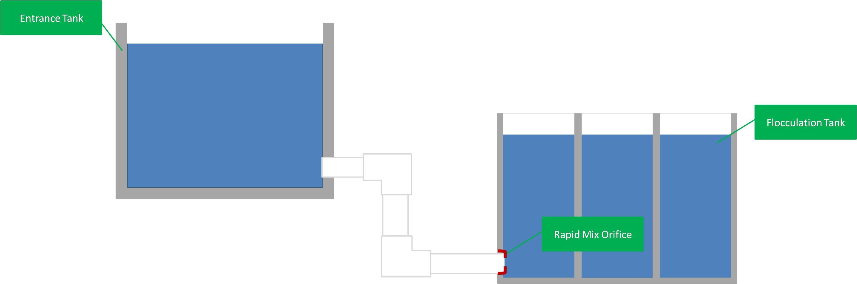
This is a diagram of the rapid mix system used before the current system was designed. This diagram points out the flaws in the previous system. | ||
| Version 1 (current) | 78 kB | user-1194e | Oct 29, 2009 10:27 | This is a diagram of the rapid mix system used before the current system was designed. This diagram points out the flaws in the previous system. | |||
| JPEG File orifice configurations.jpg | 22 kB | user-1194e | Oct 29, 2009 10:33 |
|
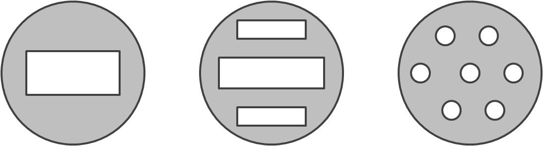
This is a diagram of several possible small scale mixing orifice configurations. | ||
| Version 1 (current) | 22 kB | user-1194e | Oct 29, 2009 10:33 | This is a diagram of several possible small scale mixing orifice configurations. | |||
| File Organized Rapid Mix Tube Design.xmcd | 303 kB | user-1194e | Oct 29, 2009 14:37 |
|
This is the new version of the MathCAD rapid mix tube design, which improves on the old file in organization of the data and calculation connections. | ||
| Version 1 (current) | 303 kB | user-1194e | Oct 29, 2009 14:37 | This is the new version of the MathCAD rapid mix tube design, which improves on the old file in organization of the data and calculation connections. | |||
| JPEG File RMTube_Tank_Schematic_labeled.jpg | 50 kB | user-1194e | Nov 30, 2009 07:27 |
|
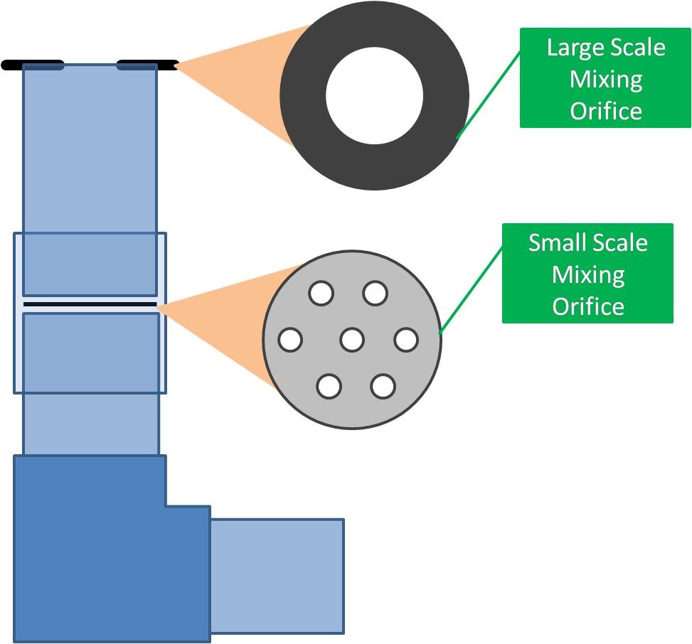
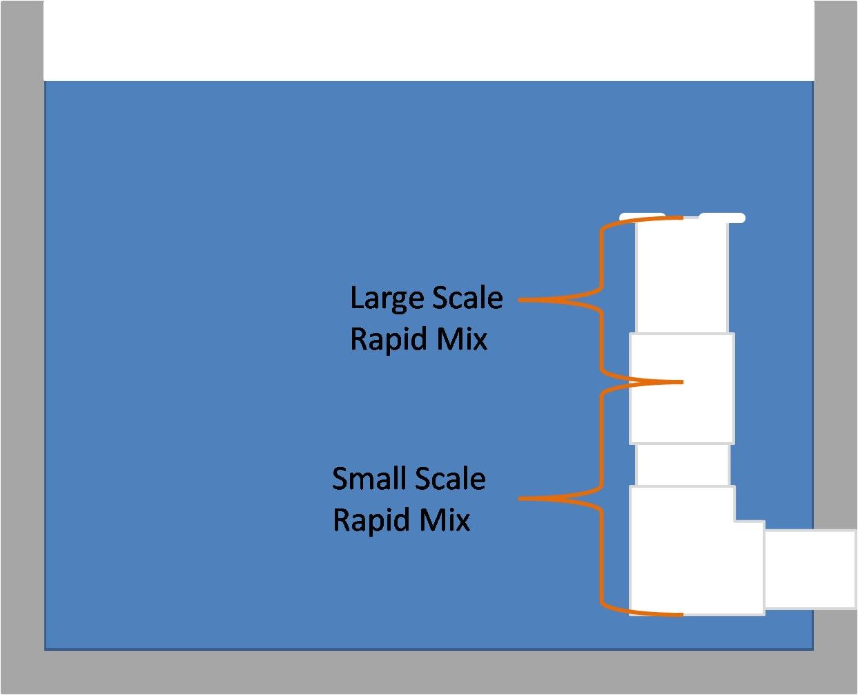
This is a schematic of the rapid mix tube with labels signifying the different functional mixing regions of the tube. | ||
| Version 1 (current) | 50 kB | user-1194e | Nov 30, 2009 07:27 | This is a schematic of the rapid mix tube with labels signifying the different functional mixing regions of the tube. | |||
| JPEG File HeadLoss v PlantFlow Plot.jpg | 30 kB | user-1194e | Nov 30, 2009 08:05 |
|
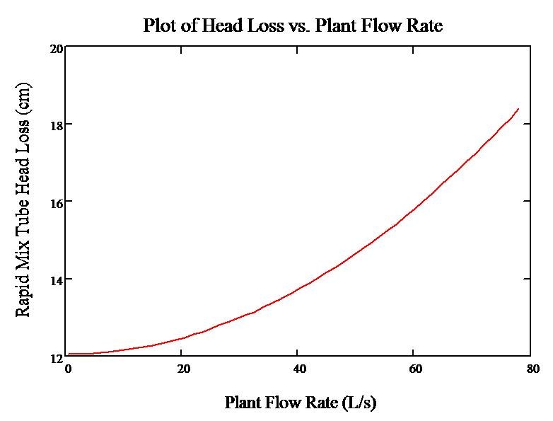
This is a plot of the head loss experienced in the rapid mix tube system as a function of varying flow rates through the tube and plant. | ||
| Version 1 (current) | 30 kB | user-1194e | Nov 30, 2009 08:05 | This is a plot of the head loss experienced in the rapid mix tube system as a function of varying flow rates through the tube and plant. | |||
| JPEG File FullTube.JPG | 2.14 MB | user-1194e | Nov 30, 2009 16:25 |
|
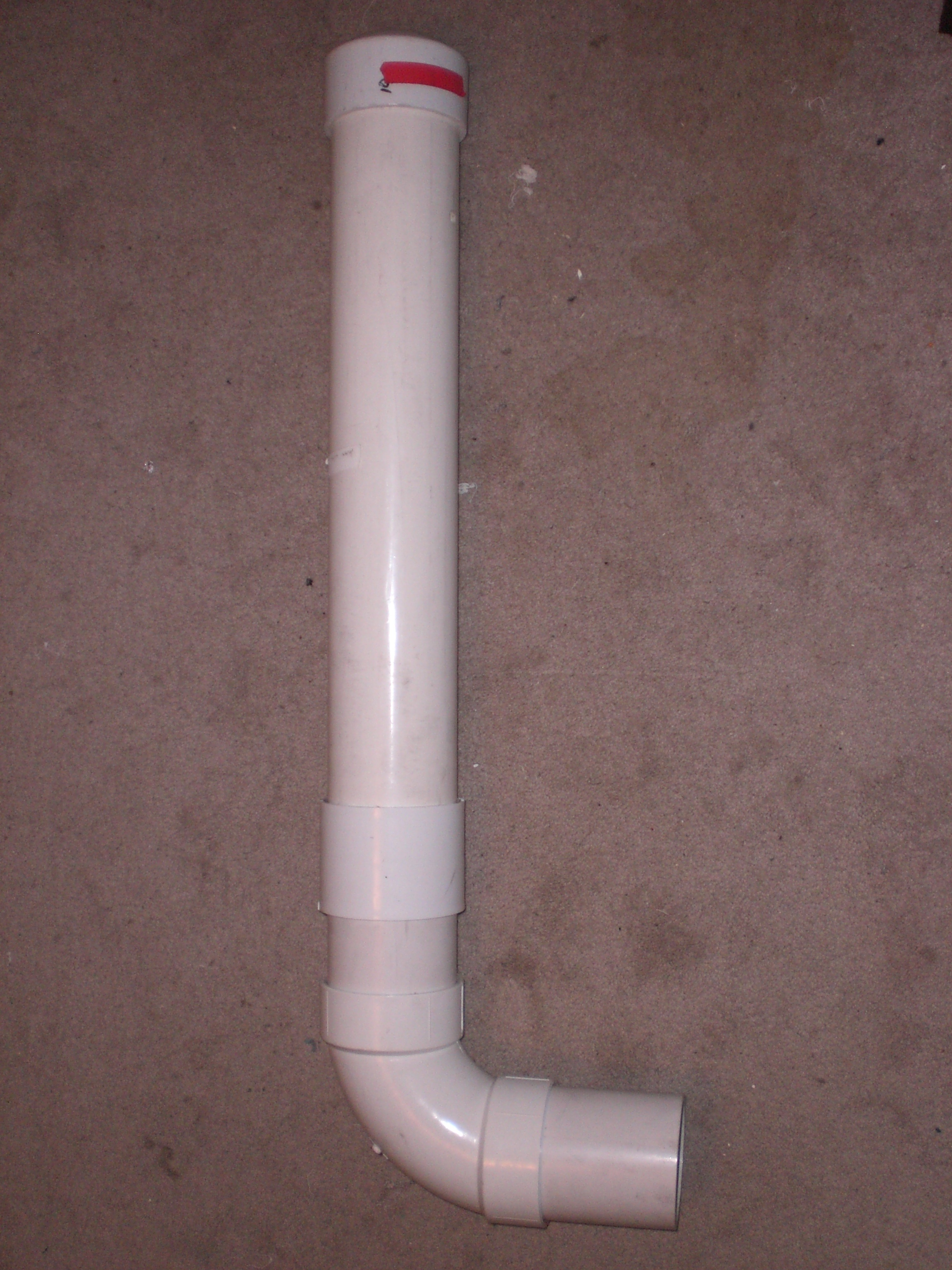
This is a photo of the full rapid mix tube when fully constructed. The ends of the tube will protrude into the entrance tank and flow out into the flocculator. | ||
| Version 1 (current) | 2.14 MB | user-1194e | Nov 30, 2009 16:25 | This is a photo of the full rapid mix tube when fully constructed. The ends of the tube will protrude into the entrance tank and flow out into the flocculator. | |||
| JPEG File SmallScaleMixingOrifice.JPG | 2.20 MB | user-1194e | Dec 01, 2009 13:52 |
|
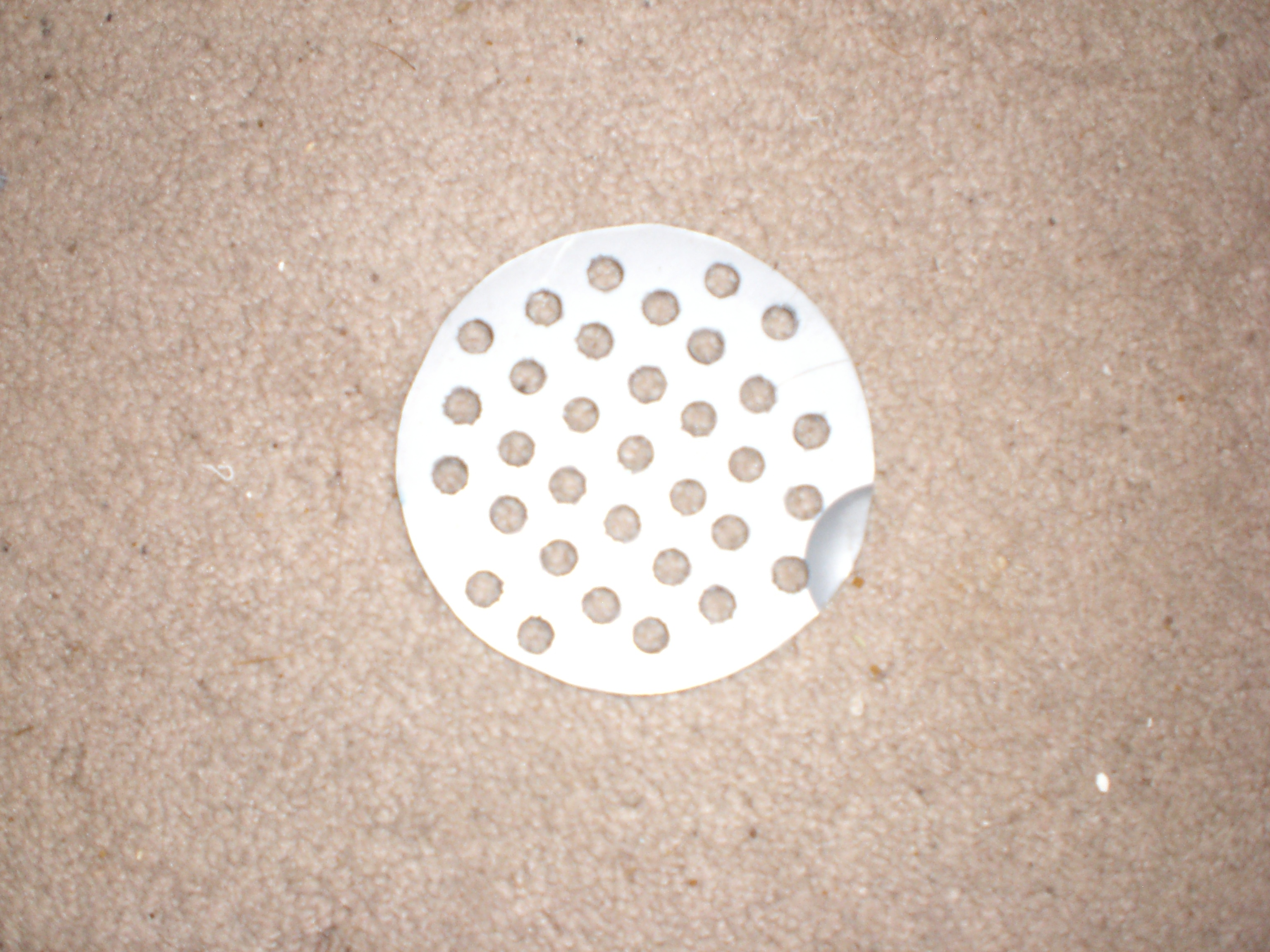
This is a photo of the small scale mixing orifice constructed for the full-scale model. It was built from a bucket lid with 5/8" holes drilled into it for the orifices. | ||
| Version 1 (current) | 2.20 MB | user-1194e | Dec 01, 2009 13:52 | This is a photo of the small scale mixing orifice constructed for the full-scale model. It was built from a bucket lid with 5/8" holes drilled into it for the orifices. | |||
| JPEG File lowerSections.JPG | 2.10 MB | user-1194e | Dec 01, 2009 13:52 |
|
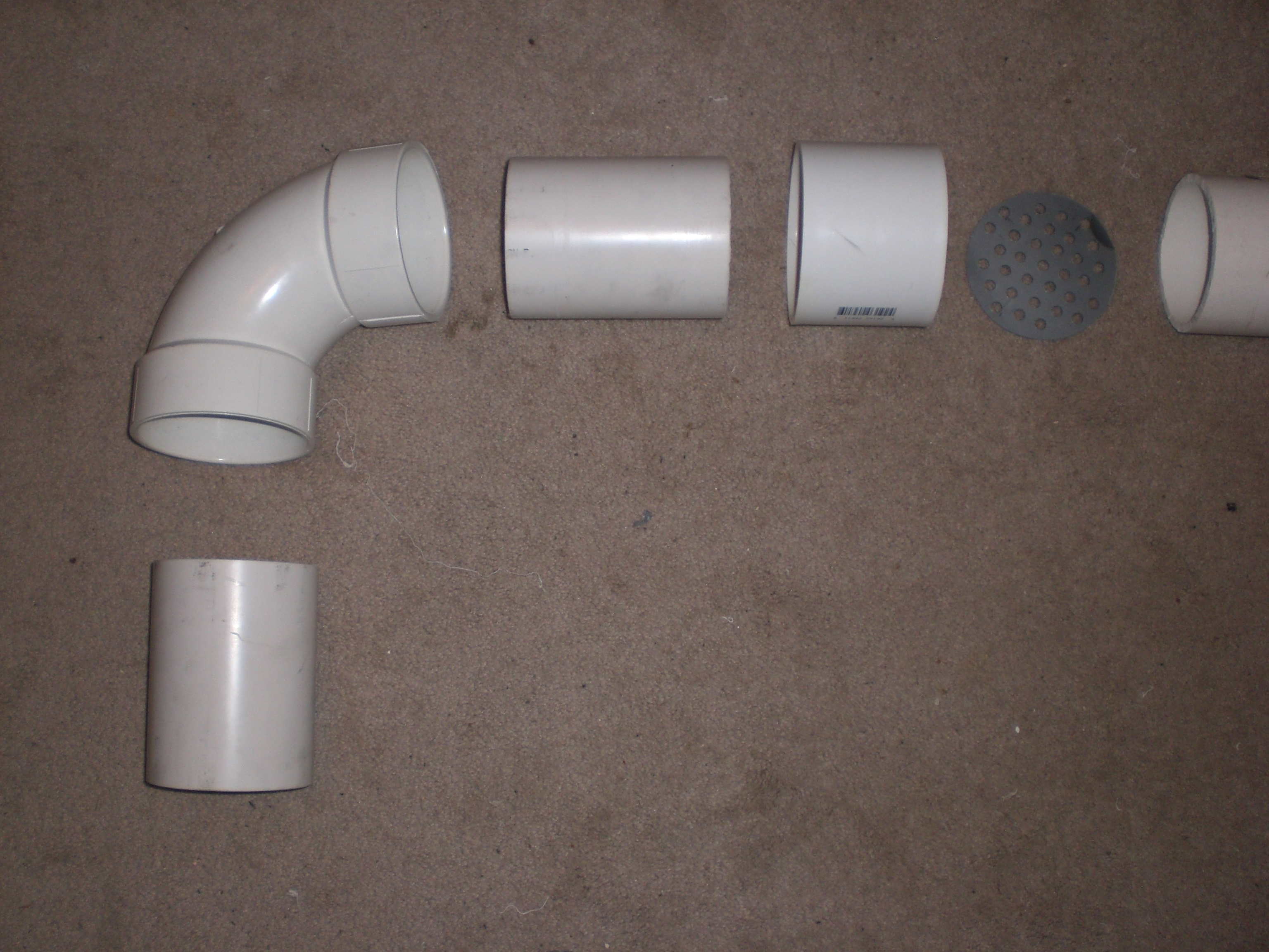
This is a photo of the lower sections of the constructed tube to show the components in greater detail. | ||
| Version 1 (current) | 2.10 MB | user-1194e | Dec 01, 2009 13:52 | This is a photo of the lower sections of the constructed tube to show the components in greater detail. | |||
| JPEG File TubeinSections.JPG | 1.57 MB | user-1194e | Dec 01, 2009 13:52 |
|
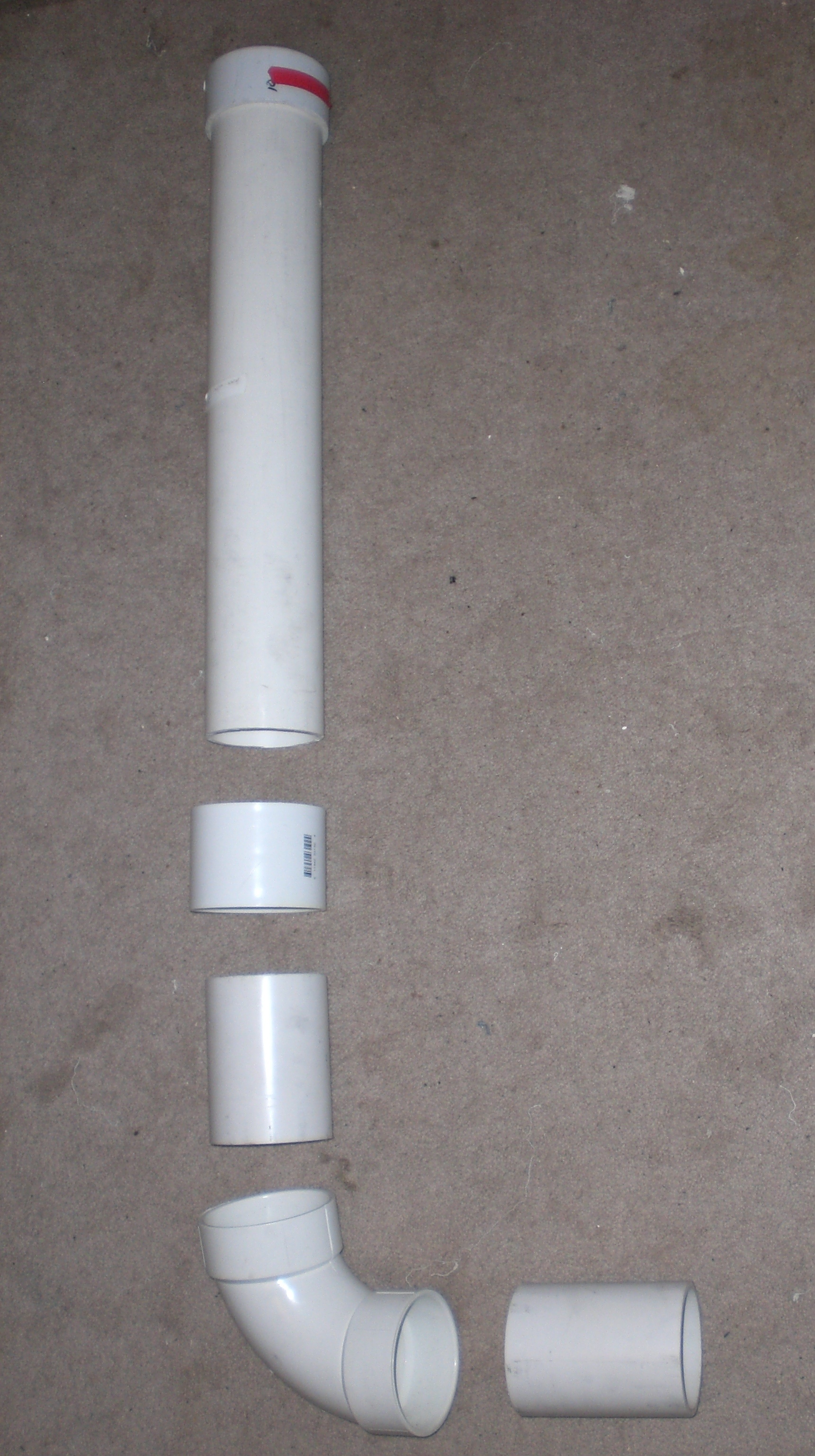
This is a photo of the constructed rapid mix tube in sections to show the construction method of the tube. | ||
| Version 1 (current) | 1.57 MB | user-1194e | Dec 01, 2009 13:52 | This is a photo of the constructed rapid mix tube in sections to show the construction method of the tube. |
Attachments
Overview
Content Tools