 Sign-up for free online course on ANSYS simulations!
Unable to render {include} The included page could not be found.
Unable to render {include} The included page could not be found.
Numerical Solution
Choosing Results
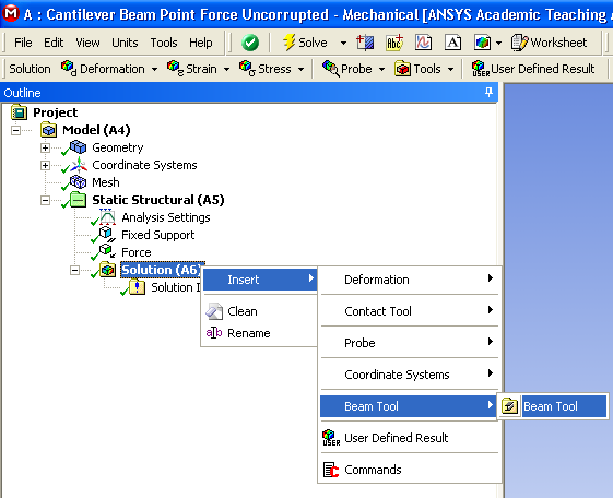
We next specify what results we'd like to look at. Note that these results can also be specified after we solve the model. First, click on the solution button,  , in the workbench window. Next, right click on the Solution (A6) folder, then click insert, then click Beam Tool and finally click Beam Tool as shown in the image below.

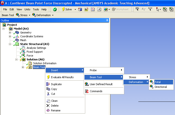
Then, right click on the Beam Tool folder that you have just added, then click on Insert, then click on Beam Tool > Deformation > Total as displayed below.

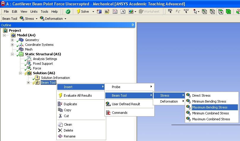
Next, right click on the Beam Tool folder, then click on Insert, then click on Beam Tool > Stress > Maximum Bending Stress as shown below.

Bending Moment along the Beam
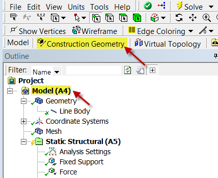
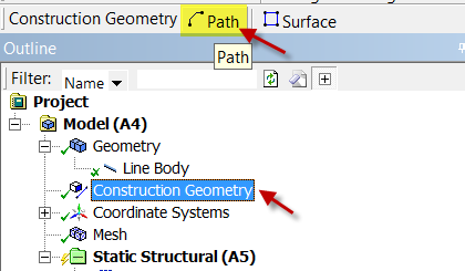
Now, we will set up a result object for the bending moment along the beam. We will do this by setting up a path along the line body. To set up a path, click on  in the Outline window. This will launch the Model toolbar in the Menu Bar. In the Model toolbar, press
  which will bring up the Construction Geometry Tool bar, then press
  to create a path.
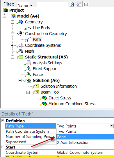
In the Details window, notice that the default path type is Two Points. We need to change that to Edge.
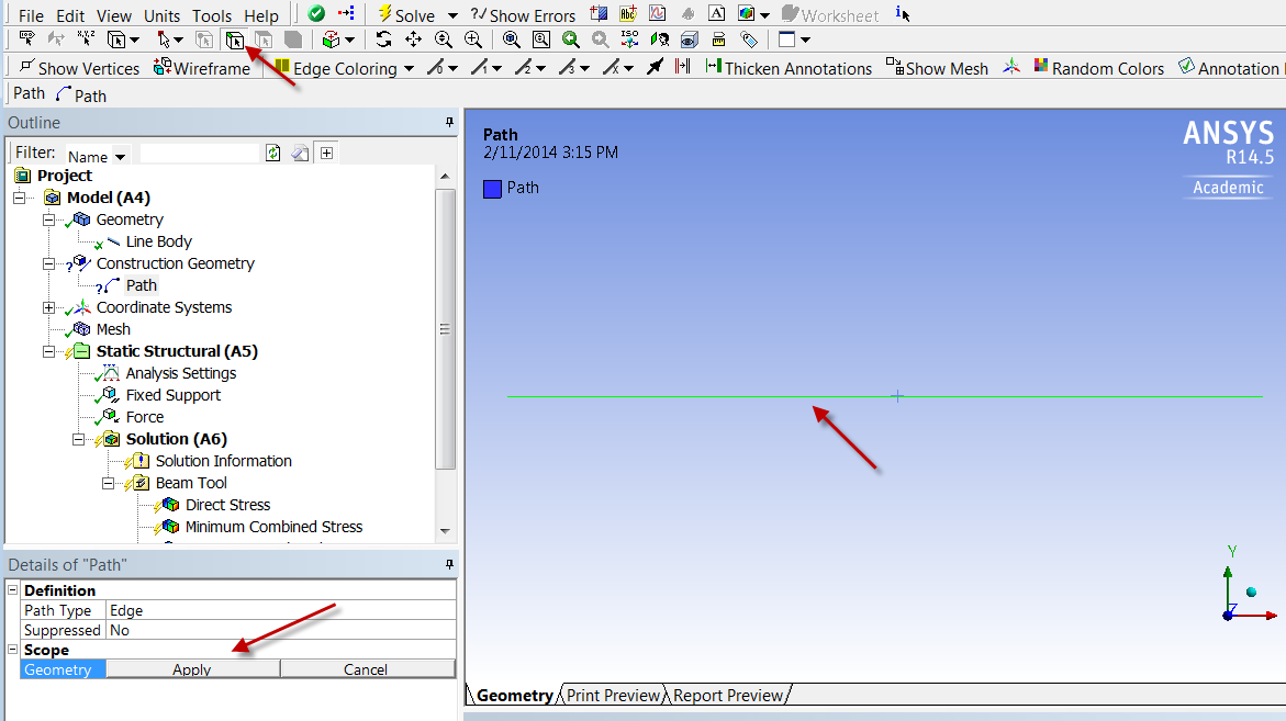
Next, using the Edge Selection filter  select the line body in the Graphics window. Back in the Details of "Path" window, select Geometry > Apply. Rename it "neutral axis".
Now that we have created the path, we need to create the solver for the bending moment along the beam. Click on in the Outline window to bring up the solution menu, then select Beam Results > Bending Moment. Now that we created the solution, we need to change the parameters so it solves along the path we created. In the Details of "Total Bending Moment" window, change Scoping Method to Path. Next, define the Path parameter to neutral axis (the path we created).

Directional Bending Moment
We would also like to look at the bending moment in a specific direction. Repeat the above step to setup another bending moment solution. In the detail window the new bending moment, change the type to Directional Bending Moment instead of the default Total Bending Moment. Change the orientation to Z axis.

Solve
In order to solve click on the solve button,  , which is located near the top of the Setup window. This process may take some time depending on the quality of the computer you are working with, so please be patient.
Go to Step 6: Numerical Results