 Sign-up for free online course on ANSYS simulations!
...
Choose areas corresponding to the plate: In the Select Entities menu, select Areas from the pull-down menu at the top. Leave By Location Location below that. Choose Z coordinates Under Min,Max, enter 0. This will select all areas whose centers lie at z=0. Make sure From Full is selected. Click Apply.
Check which areas are currently selected: Select Entities menu > Replot
Apply a pressure of 0.05 N/mm2 on the plate in the +z direction: Main Menu > Preprocessor > Loads > Define Loads > Apply > Structural > Pressure > On Areas > Pick All
For VALUE, enter 0.05. Click OK.
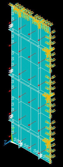
ANSYS will mark the faces where the pressure is applied. Let's instead plot the applied pressure using arrows to check its direction: Utility Menu > PlotCtrls > Symbols. For Surface Load Symbols, select Pressures and under Show pres and convect as, select Arrows. Click OK. Are the pressures acting in the right direction?
Select Entities menu: Select All, Replot and Cancel. You should now see the entire model. Review that all the BC's have been applied correctly.
Save: Toolbar > SAVE_DB
Create Log File
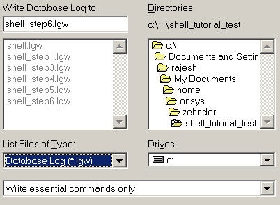
In parametric studies to be undertaken later, we'll start with the log file containing the commands from the first six steps that we just went through. To save this log file, select
Utility Menu > File > Write DB log file
Under Write Database Log to, enter the filename for the logfile: shell_step6.lgw. At the bottom of this menu, select Write Essential Commands only. Click OK. Review shell_step6.lgw by opening it in a text editor.
Go to Step 7: Solve! |
Copyright 2006. |