 Sign-up for free online course on ANSYS simulations!
| Panel |
|---|
Problem Specification |
Disks in Point Contact - Step 8]
9. Validate the results
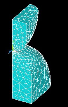
Step 5: Mesh geometry
We'll start by meshing the upper and lower disks using SOLID92 elements . Then, we'll mesh the target and contact surfaces using TARGE170 elements and CONT175 elements respectively.
...
This brings up the MeshTool.
Set Meshing Parameters
We'll now specify the element type, real constant set and material property set to be used in the meshing of the upper and lower volumes. Make sure Global is selected under Element Attributes and click on Set.
This brings up the Meshing Attributes menu. You will see that PLANE92 and material number 1 are already selected. Also, recall that no real constants need to be specified for PLANE92 element type. Click OK.
Set Mesh Size
We'll use the SmartSize option which enables automatic element sizing. Click on the SmartSize checkbox so that a tickmark appears in it. Change the setting for the overall element size level to 1 by moving the slider under SmartSize to the left.
Mesh Volumes
In the MeshTool, make sure Volumes is selected in the drop-down list next to Mesh. We'll use tetrahedral elements, so make sure the default option of Tet is selected under Shape. We'll also use the default of Free meshing.
...
In the Input window, ANSYS tells you to "pick or enter volumes to be meshed". Since both volumes are to be meshed, click on Pick All. The geometry is meshed and the elements are plotted in the Graphics window.
Mesh Target Surface
Before meshing the target surface, we need to select the nodes attached to the surface of the lower disk that are expected to come into contact with the upper disk. Since only a small area of the lower disk is expected to come into contact with the upper disk, we will select only the nodes near the point of contact and define the target surface with these nodes. To do this we will use "select logic".
...
In solving contact problems, where you expect large displacements or where you don't know where contact might occur between bodies, you want to start by selecting as many nodes as possible to capture all regions where contact may occur. At the same time, you want to keep the number of selected nodes as small as possible to reduce the time to generate a solution. Contact problems are highly nonlinear and require significant computer resources to solve. In most cases, it is best to use an iterative approach in order to reach an appropriate number of nodes and build an efficient model. |
Mesh Contact Surface
We'll now mesh the contact surface. Again, we'll start by selecting the nodes attached to the surface of the upper disk that are expected to come into contact with the lower disk. In this case, we'll select the contact area first and then the nodes attached to this area and located below the y=1.5 plane.
...
Before we move to the next step, we need to undo the selections of areas and nodes we have made. Select everything: Utility Menu > Select > Everything.
Save Your Work
Toolbar > SAVE_DB